background image


B. 

Installation 


PLEASE  READ THROUGH THE INSTALLATION  INSTRUCTIONS BEFORE 
BEGINNING THE INSTALLATION. 


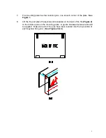
Figure 1    


1. 

Select the position of the fire on the wall to which it is to be mounted.  Draw a 

level 

horizontal line on the wall at the required height.  This line will correspond 

to the top of the appliance so it is important to allow for the extra height of the 
fire front. 

  
2. 

Mark the center line of the fire on to the horizontal line 


3. 

Place the Installation Plate supplied to the horizontal line and line up the center 
“V” cut out with the center line.  

See Figure 1.


4. 

DRYWALL INSTALLATION)  Install screws provided into studs at 4 outside 
corner screw holes.  If studs are not present, install self drilling hollow wall 
anchors provided at the 4 outside corners 

and

  find wood studs with at least 4 

more screws on the mounting plate. (2 high and 2 low)  Holes are offset to allow 
finding wood studs at normal spacing. Attach more screws into wood on 95” 
model. 


5. 

MASONRY INSTALLATION)  If the wall is of a sound masonry construction the 
attaching holes should be drilled with an 5/16” mm masonry drill. First secure the 
4 outside corners.  Use the masonry anchors and screws provided.  Double 
check that a firm solid attachement is achieved or add additional  anchors as 
required. 


6. 

If a firm attachement  cannot be   achieved it may be necessary to install extra 
support to the framing.  It is most important that the mounting plate are firm and 
solid and that the structure is capable of taking the load.   


Summary of Contents for AL 38

Page 1: ...t Package 1 1 x Electric Fire 1 x Glass Face 1 x Remote Control Handset 2 x AAA Batteries 1 x Instructions Booklet 1 x Wall Fixing Plate 1 x Fasteners Package Package 2 1 x Fire Face Stone Face Models only INSTRUCTION BOOKLET MUST BE LEFT WITH THE USER ...

Page 2: ...l and capable of taking the weight of the fire and the face 4 The fire must not be installed in an area where there is restricted air flow around the fire 5 This appliance is for indoor installation but is ok to be installed outside in fully covered installations free from damaging weather rain snow etc 6 The appliance must be kept away from any source of damp or moist conditions Avoid any close c...

Page 3: ...ner screw holes If studs are not present install self drilling hollow wall anchors provided at the 4 outside corners and find wood studs with at least 4 more screws on the mounting plate 2 high and 2 low Holes are offset to allow finding wood studs at normal spacing Attach more screws into wood on 95 model 5 MASONRY INSTALLATION If the wall is of a sound masonry construction the attaching holes sh...

Page 4: ...re 1 8 Lift the fire and place the keyhole slots situated on the back of the fire Figure 2 to the location pins on the mounting plate A gentle downward pressure should be applied Make sure all of the pins have been located into the top section of each keyhole fixing slot See Figures 3 4 ...

Page 5: ...connect the appliance to an extension cord or cable This can create an unsafe condition 5 The fire must not be modified from the manufacturer s specification in any way and the appliance must only be used for the purpose recommended by the manufacturer 6 If the fire shows any signs of damage it is important that it is examined by a qualified person 7 Please observe these instructions as failure to...

Page 6: ...re two brackets which hook over these studs 3 Lift the face up to the fire Two people may be required to carry out this installation Then lower the face into place so that the brackets on the rear of the face locate either side of the studs on the fire Once in place firmly screw into place the locking bolt Figure 6 ...

Page 7: ...ervised around the fire 4 Do not obstruct the air flow around the appliance 5 Ensure that the fire is switched off and disconnected from power source before cleaning or carrying out any maintenance work 6 When the fire is not in use it should be switched off at the main power switch 7 Do not push any objects through the vent of the fire as this may result in an electric shock or could cause a fire...

Page 8: ...the remote control handset directly towards the bottom right hand side of the fire Figure 9 B On Off Switch Press on off switch to turn fire on C Flame Effect Dimmer To operate press once to commence dimming cycle During the dimming cycle the fire will slowly dim then brighten allowing user to choose suitable level Press a second time to stop cycle when the desired brightness level is obtained Fai...

Page 9: ...icator Lamps will verify current condition If you are unsure if heat is on or off check the lamps on the control panel If the function is on the indicator lamp will light above the function switch Modern Flames Wall Hung Electric Fires TECHNICAL SPECIFICATION Model Measures WxHx D Weight volts Watts L H Remote Control AL 38 7 lbs 120 750 1500 included AL 56 56 x 27 x5 95 lbs 750 1500 included AL 9...

Page 10: ... are screws on both sides These need to be removed to allow the cover to slide down Figure 10 WARNING Allow at least five minutes for the light bulbs to cool before touching the bulbs to avoid burning Make sure power supply is disconnected Examine the bulbs to determine which one needs replacing Remove the non working bulb and replace with a new long life bulb Hold the socket while unscrewing the ...

Page 11: ...s not cover This warranty does not cover consumable items such as the bulbs and fuses which have a limited lifespan This limited warranty does not apply to products that have been repaired except by Modern Flames or its authorized service representatives or otherwise altered This warranty does further not apply to defects resulting from misuse abuse accident neglect incorrect installation water da...

Reviews: