P a g e | 14
3.4.3.2
Making Electrical Connections
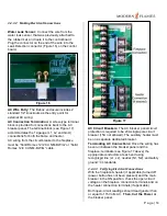
Water Leak Sensor:
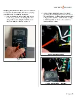
Connect the wire from the
water leak sensor, that was previously attached to
the rubber mat, and route it to the control board.
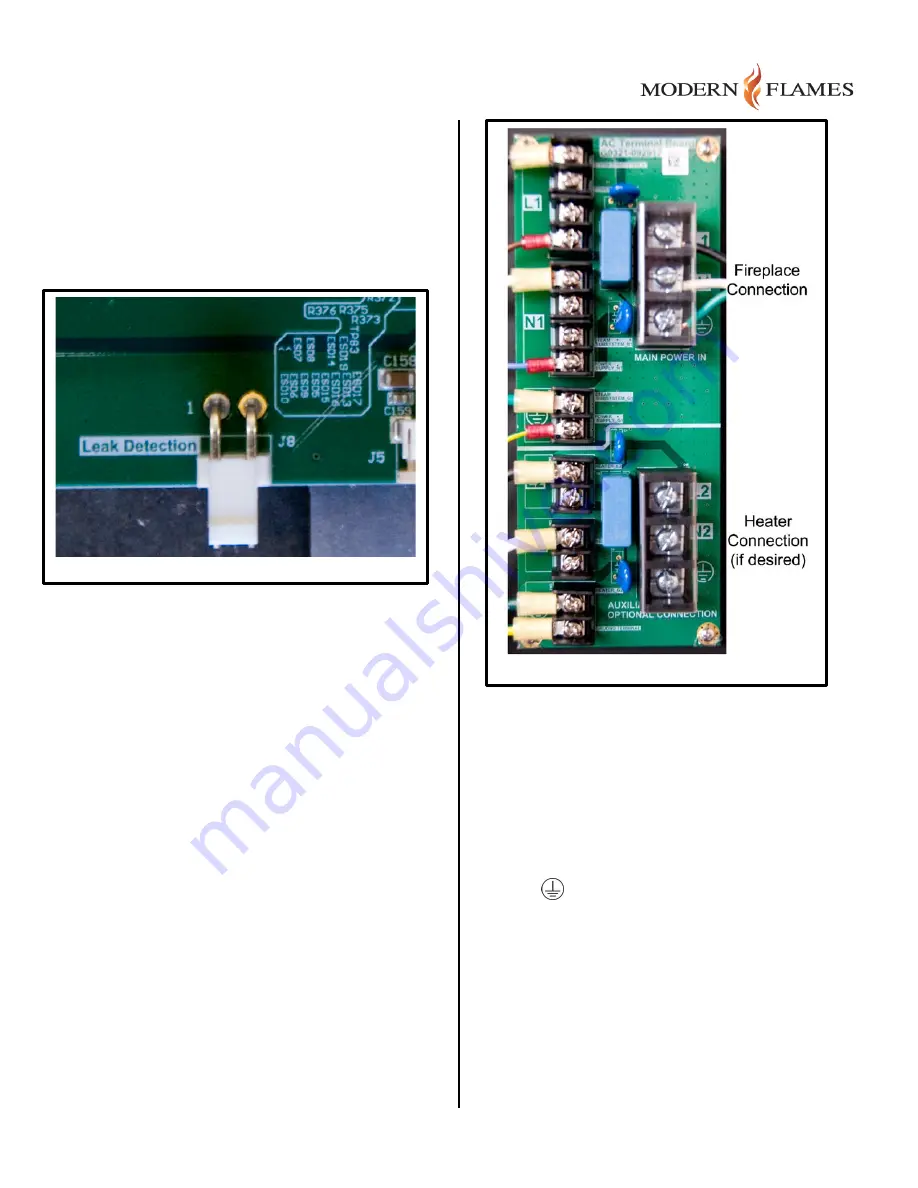
Plug the connector on the end of the wire into the
Leak Detection connector (Figure 16) on the control
board.
AC Wire Entry:
The firebox enclosure includes 2
standard 1/2" knockouts as the entry point for
external AC wiring.
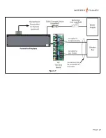
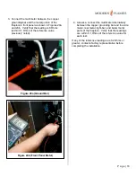
AC Connection Termination:
A screw-type terminal
block is provided for connections back to the AC
breaker panel. The terminal block (see Figure 17)
accommodates the 12-gauge (L1, L2 and Gnd.)
connections for both the flame and heater.
AC wiring from the circuit breaker to the fireplace
must be “Solid Romex 12/2 CU NM-B W/G” or “Solid
Romex 12/4 CU NM-B W/G” cable.
AC Circuit Breakers:
The AC breaker panel circuit
protection is required to be 20A single-pole circuit
breaker (15A not allowed). The auxiliary heater must
be on a separate dedicated breaker.
Terminating AC Connections:
Once the wiring has
been run between the breaker panel and the
fireplace, terminate (see Figure 17 above) the
appropriate conductors at each end using
recognized line (L1, L2), neutral (N1, N2), and safety
ground
standards.
3.4.3.3
Verifying Electrical Connections
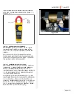
With the fireplace & heater (if applicable) turned off
(power button has not been pressed) and the main
breaker in the ON position, check the open-circuit
voltage on the fireplace connection terminals and on
the heater connection terminals (if applicable).
Both open-circuit readings should read greater than
or equal to 115 Volts AC.
Then, Cut the Power
at
the breaker panel.
Figure 16
Figure 17
Summary of Contents for FusionFire 60
Page 9: ...P a g e 9 Figure 7 ...


