P a g e | 18
If using the direct water facilities connection option
(recommended), connect the water supply and
correct possible leaks before going any further.
Once a good water connection has been verified,
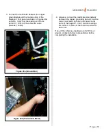
turn ON the ball valve (see Figure 23), shown in OFF
position) and monitor the flow into the reservoir.
Once the reservoir is full, the float valve will turn off
the flow automatically. Check again for leaks.
Place the black metal media bed into position and
screw into place (4 screws).
Activate the AC power by turning ON the appropriate
breaker(s) at the power panel.
3.4.5.2
Power Up
The User Display is mounted in a mechanical
“carriage mechanism”. Push the mechanism down to
release and allow viewing of the display. Push it
down again to latch and hide the display from view
(the normal operation position).
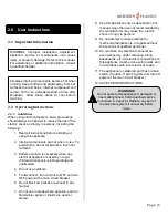
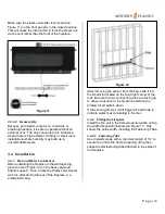
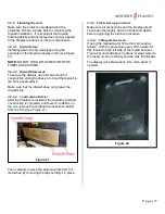
At the fireplace, with the display in the viewing
position, press the power button on the left end of
the built-in keypad (see Figure 24) to start the
fireplace.
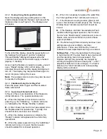
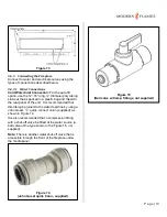
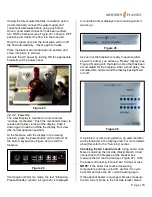
It will begin in Warm Up mode, the text “Initializing…
Please Standby” (shown in Figure 25) is displayed.
A countdown timer displays time remaining while it
warms up.
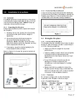
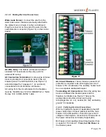
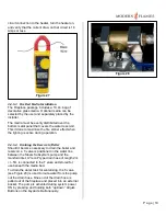
As soon as the fireplace is ready to operate (after
about 3 minutes), you will see a “Ready” display (see
Figure 26) along with the total run time that has been
accumulated for the fireplace. After a short delay, the
simulated fire will start and the display backlight will
turn off.
If a problem occurs during startup, an alert condition
will be indicated in the display area. For more details
about this refer to the “Servicing” section.
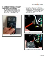
Checking the AC Load Current:
Using an AC Amp
Meter monitoring the hot side (black) branch circuit
connection to the fireplace at the breaker box,
measure the AC load current (see Figure 27). With
the boiler still heating, it should be 16 Amps or less.
NOTE:
If the boiler has reached operating
temperature and has cycled off, wait for it to cycle
back ON and take the AC current reading again.
If the optional heater is equipped, likewise measure
the AC current probe to the hot side (black) branch
Figure 24
Figure 26
Figure 23
Figure 25
Summary of Contents for FusionFire 60
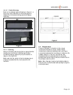
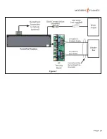
Page 9: ...P a g e 9 Figure 7 ...

