background image

ORION MULTI BUILT-IN OR WALL-MOUNT FIREPLACE 

Model #: 

….


OR52-MULTI 

…  OR60-MULTI …. OR76-MULTI 


…. OR100-MULTI …. OR120-MULTI 


OWNER’S MANUAL 


AC 120V 60Hz 1,465W (5,000BTU

’s) 

(2,930W 10,000 BTU

’s capable) 


Summary of Contents for OR100-MULTI

Page 1: ...ORION MULTI BUILT IN OR WALL MOUNT FIREPLACE Model OR52 MULTI OR60 MULTI OR76 MULTI OR100 MULTI OR120 MULTI OWNER S MANUAL AC 120V 60Hz 1 465W 5 000BTU s 2 930W 10 000 BTU s capable ...

Page 2: ...o not use in areas where gasoline paint flammable vapors or liquids are used or stored Use this heater only as described in this manual Any other use not recommended by the manufacturer may cause fire electric shock or injury to persons This heater may include an audible or visual alarm to warn that parts of the heater are getting excessively hot If the alarm sounds or illuminates immediately turn...

Page 3: ... result in electric arcing within the outlet that could cause the outlet to overheat or catch fire ALWAYS check your heater cord and plug connections with each use i MAKE SURE the plug fits tightly in the outlet Faulty wall outlet connections or loose plugs can cause the outlet to overheat ii Heaters draw more current than small appliances Overheating may occur even if it has not occurred with the...

Page 4: ...ED GLASS INSTALLATION 19 OPERATION CONTINUED 20 OPERATION 21 OPERATION TOUCH CONTROL PANEL 22 OPERATION REMOTE CONTROL 23 DOWNLOAD SMART PHONE APP 25 WI FI INITIAL LOG IN 26 WI FI PAIRING 27 Add Manually 27 Auto Scan 30 OPERATION SMART PHONE APP 33 HOME SCREEN 33 FLAME STYLE OPTIONS 34 FLAME STYLE ONE TWO THREE COLOR MENU 35 DOWNLIGHT MENU 36 EMBER BED MENU 37 HEATER MENU 38 TIMER MENU 39 WEEKLY P...

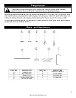
Page 5: ...er possible You will need the following tools not included Phillips screwdriver stud finder level tape measure electric drill 1 4 wood drill bit hammer Parts and Hardware PART NO DESCRIPTION PART NO DESCRIPTION A Screws Long F Wall Mount Bracket B Drywall Anchor G Crushed Glass C Screws Short H Driftwood Logs D Terminal Block Screw I Drywall Stop E Remote Control This product includes a GLASS pane...

Page 6: ...3 16 132mm OR100 MULTI 100 2542mm 24 5 16 618mm 9 9 16 240mm 99 1 4 2521mm 23 7 8 606mm 8 15 16 143mm 98 3 4 2508mm 18 7 16 468mm 2 52mm 3 7 16 87mm 5 3 16 132mm OR120 MULTI 124 3 8 3159mm 24 5 16 618mm 9 9 16 240mm 123 1 2 3137mm 23 7 8 606mm 8 15 16 143mm 123 3125mm 18 7 16 468mm 2 52mm 3 7 16 87mm 5 3 16 132mm Installation and Assembly Your appliance is a wall mounted recessed and or mantel ins...

Page 7: ...y tilt the top edge of the glass away from the appliance Fig 1 2 Once the top edge of the glass is free from the fireplace lift on the glass to fully remove it Place the glass on a soft non abrasive surface For the larger configurations it may require multiple people to safely remove the glass Reverse these steps to re install the front glass This product includes a GLASS panel Always use extreme ...

Page 8: ... com Built In Installation Styles Optional Built In styles shown below See Partial Recess Installation or Wall Mounted Installation for additional mounting styles 2 Sided Right or Left Exposed 3 Sided Bay Built In Single Sided ...

Page 9: ...ensions Electrical to be at the top right of the rough in framing Remove the front glass see Glass Removal Installation section Hold the appliance up to ensure it will fit into the framing ROUGH OPENING FRAMING DIMENSIONS Model Number A B C Fully Recessed OR52 MULTI 51 1295mm 24 3 4 629mm 9 min 229mm min OR60 MULTI 59 1 2 1511mm 24 3 4 629mm 9 min 229mm min OR76 MULTI 75 1 4 1911mm 24 3 4 629mm 9 ...

Page 10: ...elected Ensure an appropriate dedicated power circuit is provided at the top right of the framed opening Remove the front glass See Glass Removal Installation Install the L Metal Nailing Flanges to both the top and bottom of the fireplace Fig 2 1 Quantities of L Metal Nailing Flanges will change depending on fireplace size ordered Note that the location of the L bracket will change if partial inst...

Page 11: ...e Install the drywall stops shipped loose where the side plates where Store the side plates in a safe place Hardwire the fireplace to the dedicated power circuit see Hardwiring Installation Install the fireplace in the framed opening Adjust the adjustable feet as needed to ensure the fireplace is level Fasten the fireplace to the framing using the L Metal Nailing Flanges and drywall screws that ha...

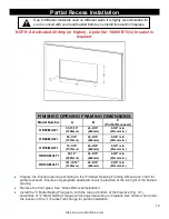
Page 12: ...m 2 5 8 min 67mm min Prepare the finished opening according to the Finished Opening Framing Dimensions chart for partial recessed Ensure an appropriate dedicated circuit is provided at the top right of the framed opening Remove the front glass See Glass Removal Installation Install the L Metal Nailing Flanges to both the top and bottom of the fireplace Fig 3 1 Quantities of L Metal Nailing Flanges...

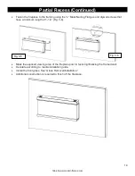
Page 13: ...oth sides of the fireplace Fig 3 4 Remove the side plates from both sides of the fireplace Store the plates in a safe place Install the side trim to both sides of the fireplace Hardwire the fireplace to the dedicated circuit see Hardwiring Installation Install the fireplace in the framed opening Adjust the adjustable feet as needed to ensure the fireplace is level Fig 3 5 Partial Recess Built In R...

Page 14: ...rywall screws that have a minimum length of 1 1 4 Fig 3 6 Mask the exposed viewing area of the fireplace prior to texturing finalizing the framed wall Decorate according to media installation guide Install the front glass See Glass Removal Installation Additional construction is required to finish off the fireplace Fig 3 5 Fig 3 6 ...

Page 15: ...You must be able to secure to a minimum of 2 studs for proper installation of the bracket Using the wall bracket as a guide mark the mounting hole locations This bracket MUST have the hooks facing upward and be level Fig 4 2 Additional support is provided by using the included wall anchors B between the studs Additional wall anchors must be installed prior to the wall bracket being mounted i To in...

Page 16: ...wall mounting bracket installed have two people lift the appliance up and insert the two hooks of the wall bracket into the two receiver slots on the back of the appliance Fig 4 4 Re insert the two wall mount bracket screws that were removed previously Check the appliance for stability ensuring the bracket will not pull free from the wall Wall Mount Cabinet Suite sold separately may now be install...

Page 17: ...ational Electrical Code in the USA 120 Volt Power 5 000 BTU s Note There are 3 wires from the appliance junction box white neutral black power L1 and green bare ground that are connected to 120V power source circuit breaker panel Ensure power from the circuit breaker is off Remove the 2 securing screws from the junction box cover plate located on the top left hand back side of the appliance Fig 5 ...

Page 18: ...r panel Ensure that power from the circuit breaker is off Remove the 2 securing screws from the junction box cover plate located on the top left hand back side of the appliance Fig 6 1 In the hardware kit locate the terminal screw with accompanied clamp plate D that match the existing screws and clamp plates of the terminal block Screw the terminal screw into the open position of the terminal bloc...

Page 19: ...ared by sliding the crushed glass along the channel until it falls into one of the cleanout slots Photos below shows recommended log placement but logs may be arranged to customer s liking Log placement shown in top down orientation ORION MULTI 52 LOG PLACEMENT v ORION MULTI 60 LOG PLACEMENT ORION MULTI 76 LOG PLACEMENT ORION MULTI 100 LOG PLACEMENT ORION MULTI 120 LOG PLACEMENT 14 14 14 14 9 9 9 ...

Page 20: ... After resetting the Master Power Switch or from a loss of power the fireplace takes 20 30 seconds before the fireplace is fully booted and operational Pairing the Remote With the fireplace ON press and hold the Power button for 5 seconds until you hear a beep from the fireplace P1 will be shown on the display Within 5 seconds of the fireplace beeping repeatedly press the power button on the remot...

Page 21: ...on This electric fireplace can be operated by the TOUCH CONTROL PANEL located on the UPPER right corner of the fireplace by the battery powered REMOTE CONTROL or by the MODERN FLAMES APP using a smart phone Touch Control Panel Remote Control Modern Flames App ...

Page 22: ...es of flame with six colors for each flame 1C 2C 3C 4C 5C 6C NOTE Press and hold for 5 seconds to start connecting with App HEATER BUTTON Turns heater on and off NOTE The heater only works when the flame is on If the flame is off the heater will not turn on NOTE To prevent overheating the heater fan will blow cool air for 8 10 seconds after the heater turns off 1 Press once Turns the heater and bl...

Page 23: ... for 5 seconds enables Wi Fi pairing mode 3 Press ʌ once Changes up to the next preset of current flame style 4 Press ʌ again until desired preset is selected from 1C 2C 3C 4C 5C 6C 5 Press v once Changes down to the next preset of current flame style 6 Press v again until desired preset is selected from 6C 5C 4C 3C 2C 1C 7 Press button to increase the flame speed Displayed 01 02 03 8 Press button...

Page 24: ...al 5 levels From E4 E3 E2 E1 E0 off TIMER BUTTON Controls timer settings to turn off fireplace at selected time Settings range from 30 min to 8 hours 1 Press once Indicator light turns on Timer defaults to 0 5 hours 2 Press again until desired setting is reached 00 off 30 1H 2H 3H 4H 5H 6H 7H 8H HEATER BUTTON Turns heater on and off NOTE The heater only works when the flame is on If the flame is o...

Page 25: ...25 https www modernflames com Download Smart Phone App Smart Phone App Connection Note Download the Modern Flames App from your App store before connecting Download Mobile App ...

Page 26: ...l the Modern Flames app from the Google Play or Apple App store or scan the QR code on the previous page After the App is installed log in to the Modern Flames App Must have Wi Fi and Bluetooth enabled on your smart phone Once opened from the home page select the add symbol ...

Page 27: ... Add Manually Select the series of fireplace that will be paired with and follow the instructions When pairing via Wi Fi the 2 4 GHz Wi Fi signal must be used Ensure the appropriate login information is entered before continuing to the next step ...

Page 28: ...ode the fireplace will display P0 ii In AP Mode the fireplace will display P2 iii Holding the flame button for an additional 5 seconds will cycle the fireplace between EZ Mode and AP Mode Device and APP should now begin to pair Depending on Wi Fi this can take up to two minutes to pair and may need to be repeated more than once ...

Page 29: ...disconnect the fireplace from power while pairing the Wi Fi or performing updates Failure to do so can result in damage to electrical components of the fireplace Damage as a result of this may not be covered under warranty Questions or assistance in pairing device contact Modern Flames at customerservice modernflames com or call 877 246 9653 Monday Friday 8 00 am 5 00 pm MST ...

Page 30: ...Fi Pairing Continued Auto Scan Select auto scan from the top of the App On the fireplace touch controls press and hold the Flame button for 5 seconds The fireplace will show either P0 or P2 This will place the fireplace in pairing mode ...

Page 31: ...fireplace select the Next button if the app does not proceed automatically If the scan fails to find a fireplace press and hold the Flame button on the manual touch controls to switch pairing modes Enter in the Wi Fi information The information must be entered to be able to proceed to the next step The App will begin connecting ...

Page 32: ...disconnect the fireplace from power while pairing the Wi Fi or performing updates Failure to do so can result in damage to electrical components of the fireplace Damage as a result of this may not be covered under warranty Questions or assistance in pairing device contact Modern Flames at customerservice modernflames com or call 877 246 9653 Monday Friday 8 00 am 5 00 pm MST ...

Page 33: ...eed Slider Changes the flame speed of currently displayed flame Cycles between SLOW DEFAULT and FAST 1 Slide to the Slow position Flame moves at the slowest speed Fireplace displays 01 2 Slide to the Default position Flame moves at the default speed Fireplace displays 02 3 Slide to the Fast position Flame moves at the fastest speed Fireplace displays 03 5 Flame Volume Slider Changes the sound effe...

Page 34: ...Opens a new page to make changes to the heater settings 9 Timer Button Opens the timer sub menu 1 Press once Opens the timer sub menu for various timer related functions Flame Style Options Button Function Action 3 1 Return Button Returns to the previous page 1 Press once Returns to the previous page 3 2 Style One Button Opens the flame style one sub menu 1 Press once Opens the flame style one sub...

Page 35: ...fireplace to the Orange flame Ember bed and downlighting change to the designated preset 3 2 4 Blue Flame Button Changes the fireplace to the Blue flame 1 Press once Changes the fireplace to the Blue flame Ember bed and downlighting change to the designated preset 3 2 5 Green Flame Button Changes the fireplace to the Green flame 1 Press once Changes the fireplace to the Green flame Ember bed and d...

Page 36: ...nlighting 1 Sliding to the left dark Dims the brightness of the downlight 2 Sliding to the right light Brightens the downlight 6 4 Color Cycle Slider Cycles the downlight colors between all colors shown on the color wheel 1 Slide to OFF position Downlight stays a solid color 2 Slide to ON Infinity position Downlight cycles between the 10 colors shown on the color wheel 6 5 Night Mode Slider Enable...

Page 37: ...ness of the ember bed 1 Sliding to the left dark Dims the brightness of the ember bed 2 Sliding to the right light Brightens the ember bed 7 4 Color Cycle Slider Cycles the ember bed colors between all colors shown on the color wheel 1 Slide to OFF position Ember bed stays a solid color 2 Slide to ON Infinity position Ember bed cycles between all colors shown on the color wheel 7 5 Accessory Mode ...

Page 38: ...Celsius 8 4 Thermostat Temperature Slider Changes the thermostat value of the fireplace enabling or disabling the heater at the set temperature 1 Slide to preset position Changes the thermostat to the selected number Heater will turn on until the ambient temperature reaches the selected thermostat value Heater will turn off once the ambient temperature is equal to or greater than the thermostat va...

Page 39: ...imer reaches zero 1 Press once No action 9 3 Preset Timer Options Changes the amount of time for the fireplace to run before turning off 1 Slide to preset position Changes the timer to the selected number The fireplace will turn off once the timer reaches zero 2 Sliding to 00 position Turns the timer off The fireplace will stay on until the user manually turns off the fireplace 9 4 Weekly Program ...

Page 40: ...Days Displays if a day has a program assigned to it Selecting a day will open that day s sub menu 1 Press on a day once Opens that day s sub menu 9 4 3 Color Key Shows the meaning of the different color codes used in the daily programming 1 Press once No action 9 4 4 Reset Button Clears the programming from ALL days 1 Press once Clears the programming from ALL days All days revert to default state...

Page 41: ... the same time as any other programming mode Note The app prevents from scheduling conflicting modes Note Manual settings supersede programmed settings 9 4 2 3 Color Key Shows the meaning of the different color codes used in the daily programming 1 Press Off once Allows to schedule the fireplace to turn off 2 Press Heater On once Allows to schedule the fireplace to turn the heater on until the amb...

Page 42: ...ded Apply power to the fireplace If problem continues have the wiring and outlet inspected by a professional Care Cleaning Metal Clean using a soft cloth slightly dampened with soapy water DO NOT use a brass polish or household cleaners as these products will damage the metal trim Glass Use an ammonia free glass cleaner sprayed onto a cloth or towel Dry thoroughly with a paper towel or lint free c...

Page 43: ...e consumer Storage Store the fireplace in a clean dry place when not in use Risk of electric shock Do not open any panels No user serviceable parts inside Always turn the heater OFF and unplug power cord from the outlet before cleaning performing maintenance or moving this fireplace Failure to do so could result in electric shock fire or personal injury WARNING NO SERVICING of the internal or elec...

Page 44: ...9 Downlight Bracket 02 00516 02 00517 02 00518 02 00519 02 00520 10 Front Glass 04 00053 04 00054 04 00055 04 00056 04 00057 11 Front Glass Bracket 02 00521 12 Side Glass Bracket 02 00522 13 Acrylic Ember Bed 03 00080 03 00081 03 00082 03 00083 03 00084 14 Ember Bed Accessory 01 00123 15 Heater Mount Bracket 02 00523 16 Power Board 01 00104 01 00105 17 Main Circuit Board 01 00106 18 USB Receiver 0...

Page 45: ...34 Terminal Block 01 00114 35 Terminal Block Cover 02 00532 36 Wall Bracket 02 00400 02 00401 02 00402 02 00403 02 00533 37 Bottom Screen Support 02 00534 02 00535 02 00536 02 00537 02 00538 38 Side Screen Support 02 00539 39 Top Screen Support 02 00540 02 00541 02 00542 02 00543 02 00544 40 Virtual Screen 01 00100 41 Access Panel Right 02 00545 02 00546 02 00547 02 00548 02 00549 42 Access Panel ...

Page 46: ...g Orion 3 05 00067 50 Log Orion 4 N A 05 00068 51 Log Orion 5 05 00069 52 Log Orion 6 05 00070 53 Log Orion 7 N A 05 00071 54 Log Orion 8 05 00072 55 Log Orion 9 05 00073 56 Log Orion 10 N A 05 00074 57 Log Orion 11 N A 05 00075 58 Log Orion 12 N A 05 00076 59 Log Orion 13 N A 05 00077 60 Log Orion 14 05 00078 61 Log Orion 15 N A 05 00079 62 Log Orion 16 N A 05 00080 63 Log Orion 18 N A 05 00082 ...

Page 47: ... Service for support 1 877 246 9353 Fireplace has overheated and the safety thermal switch has tripped Unplug power or turn off the circuit breaker Allow fireplace to cool for 15 minutes and then plug in the fireplace or turn the breaker back on Remote control does not work Low dead batteries Replace the batteries in the remote control Remote receiver malfunction Ensure the remote receiver is not ...

Page 48: ...ames Customer Service for support 1 877 246 9353 Main PCB board issue Inspect circuit boards for loose connections or obvious damage Call Modern Flames Customer Service for support 1 877 246 9353 No difference from setting H1 to H2 Main PCB board issues Inspect circuit boards for loose connections or obvious damage Call Modern Flames Customer Service for support 1 877 246 9353 Heating element issu...

Page 49: ...immediate help with installation product information or if your product arrives damaged please call our toll free number at 1 877 246 9353 Monday Friday 8 00AM 5 00PM AZ Mountain Time Or email us at customerservice modernflames com OUR STAFF IS READY TO PROVIDE ASSISTANCE ...

Reviews: