background image

FR-D2102

Ultra Germicidal Smart Fan Instructions

18

6. Finishing the Installation

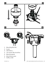
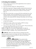
1.  Secure all wire connections with supplied wire ties to assist in 

canopy installation.

2.  Tuck connections neatly into ceiling outlet box.

3.  Slide the canopy up to hanger bracket and place the key hole on 

the canopy over the screw on the hanger bracket. Turn canopy 
until it locks in place at the narrow section of the key holes. 
(Fig. 6)

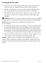
4.  Align the circular hole on canopy with the remaining hole on the 

hanger bracket. Secure by tightening the one screw previously 
loosened and the one previously removed. Adjust the canopy 
screws as necessary until the canopy and canopy cover are snug. 
(Fig. 6)

5.  Carefully read and remove the UV Warning sticker from the glass 

on top of UV module.

6.  Adjust the canopy screws as necessary until the canopy  

and canopy screw ring are snug. (Fig. 6)

7.  You are now ready to power on your fan and UV.  Please follow the 

UV Safety Rules before turning on your fan. 


WARNING:


This product emits 

ultraviolet (UV) radiation. Exposure to UV radiation can 
cause serious personal injuries, including damage to 
eyes and skin. Do not operate the product while anyone 
could be directly exposed to the UV light. For more safety 
instructions, please refer to page 5 of this instruction 
manual (“UV Saefty Rules”).

NOTE:  

UV light will not operate independently from fan for 

safety and efficacy reasons.  The violet indicators will illuminate 
when the UV light is enabled.  They cannot be turned off.

 WARNING: 

 Make sure tab at bottom of hanger bracket is 

properly seated in groove of hanger ball before attaching canopy 
to bracket. Failure to properly seat tab in groove could cause 
damage to  electrical wiring.

Summary of Contents for Ultra

Page 1: ...Ultra Germicidal Smart Fan Installation Instructions works with the Google Assistant ...

Page 2: ...FR D2102 Ultra Germicidal Smart Fan Instructions 2 Please read and save these instructions before installation DO NOT RETURN TO STORE ...

Page 3: ...arts or general inquiries call our trained technical staff at 1 866 810 6615 option 0 MON FRI 8AM 8PM EST Email customerservice modernforms com Or live chat at modernforms com For fast service have the following information below when you call 1 Model Name and Number 2 Part Number and Part Description 3 Date Of Purchase and Purchase Location 1 866 810 6615 option 1 MON FRI 8AM 8PM EST Email fansup...

Page 4: ...ecessary before installation WARNING Do not install or use your fan if any part s is are damaged or missing This product is designed for use only with the supplied parts and or accessories designated for use with this product by Modern Forms Substitution of parts or accessories not designated for use with this product by Modern Forms could result in personal injury or property damage and will void...

Page 5: ...r of paint that has not been UV stabilized Fading or discoloration of materials directly exposed to UV radiation should be considered normal wear Black is the least reflective color and white is the most reflective color WARNING It is the responsibility of the installer to ensure that persons will not be directly exposed to UV or optical radiation during equipment operation This will require the i...

Page 6: ...cessories DC MOTOR complement high quality materials personalize your experience Quiet reliable and up to 70 more efficient than AC fans Wi Fi and Bluetooth enabled for flexible control Bluetooth Remote Control ON OFF 6 fan speeds F RCUV WT White Wet Location listed to the strictest UL cUL safety regulations Finished and rated for interior and exterior use ULTRA VIOLET ...

Page 7: ...he Mounting Bracket 12 3 Hanging the Fan 12 3 Hanging the Fan cont 14 4 Attaching the Fan Blade 14 5 Making the Electrical Connections 16 6 Finishing the Installation 18 7 Controlling the Fan 20 21 8 Reset 22 9 Breeze Mode 22 10 Application 22 11 Accessories 24 12 Troubleshooting 24 13 Troubleshooting cont 25 28 ...

Page 8: ...n all parts have been removed Place the parts from the hardware bag into a small container to keep them from being lost Part A Part B Part C Part D Hardware Bag RPL F2102 PARTS Hardware Bag RPL F2102 PARTS 10 x 38mm Pan Head Phillip Screws 2 10x76mm Pan Head Phillip Wood Screws 1 8 3 16 5 2x8 4x1 0mm Spring Washer 1 6 5x19x2mm Flat Washer 1 5 5x12x1mm Flat Washer 10 3 16 Star Washer 2 3 16 6mm Phi...

Page 9: ...FR D2102 Ultra Germicidal Smart Fan Instructions 9 IMPORTANT Please make note of the MAC ID on the receiver and keep it in a safe place MAC ID 7 1 3 6 4 5 5A 2 Hanging Weight 20 lbs ...

Page 10: ...let boxes Use only UL cUL listed outlet boxes marked FOR FAN SUPPORT Secure the outlet box directly to the building structure Use Part A if needed Figures 1 1C are examples of different ways to mount the outlet box NOTE To hang your fan where there is an existing fixture but no ceiling joist you may need an installation hanger bar NOTE Downrod fans can be suspended up to a maximum recommended leng...

Page 11: ...ra Germicidal Smart Fan Instructions 11 1 1A 1B 1C 1 1 2 1 1 2 3 3 1 Support Brace 2 Outlet Box 3 Joist 1 Support Brace 2 Mounting Bracket 3 Recess Outlet Box 1 Outlet Box 1 Outlet Box Support Ceiling Max 30 Angle ...

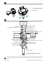
Page 12: ...e cross pin Remove the hanger ball from the hanger ball downrod assembly Fig 4 You may use the optional 6 inch rod if you prefer The 10 inch rod is optimal for airflow production and replacing the UV module in the future 2 Remove the clevis pin and cotter pin and loosen the two collar screws from the motor collar 3 Feed motor wires and safety cable through coupling cover canopy ring and canopy Fig...

Page 13: ...ions 13 2 2A 3 4 1 Mounting Bracket 2 Screw 1 2 2 3 1 To Switch A A B HOT Neutral HOT Switch No Neutral Ground Bare or Green Ground Bare or Green To Switch 1 cUL Listed Electrical Box 2 Mounting Screws outlet box screws not included 3 120V Wires ...

Page 14: ...e fan loosening and possibly falling NOTE Make sure all screws are tightened and that wires are not twisted 8 Carefully lift the fan motor assembly up to the mounting bracket and seat the hanger ball in the mounting bracket socket Make sure the tab on the mounting bracket socket is properly seated in the groove in the hanger ball Rotate the socket assembly until the ball drops and locks into the h...

Page 15: ...FR D2102 Ultra Germicidal Smart Fan Instructions 15 4A 4B 4D 4C 1 Mounting Bracket 2 Screw 3 120V Wires 4 cUL Listed Electrical Box 5 Mounting plate 6 Mounting screws 7 Safety cable ...

Page 16: ...t box WARNING Failure to connect ground wires could result in poor fan control functionality 2 Connect the red wire from the fan to the red wire marked TO MOTOR from the receiver 3 Connect the grey wire from the fan to the grey wire marked TO MOTOR from the receiver 4 Connect the yellow wire from the fan to the yellow wire marked TO MOTOR from the receiver 5 Connect the white wire from the fan to ...

Page 17: ...r GREY to Motor WHITE Neutral WHITE to Light WHITE Neutral Safety Cable GREY to Motor YELLOW to Motor WHITE Line in N YELLOW to Motor Outlet Box Receiver Hanger Ball Downrod Hanger Bracket Follow the steps above to connect the fan to your household wiring Use the plastic wire nuts with your fan Secure the plastic wire nuts with electrical tape Make sure there are no loose strands or connections Us...

Page 18: ... on top of UV module 6 Adjust the canopy screws as necessary until the canopy and canopy screw ring are snug Fig 6 7 You are now ready to power on your fan and UV Please follow the UV Safety Rules before turning on your fan WARNING This product emits ultraviolet UV radiation Exposure to UV radiation can cause serious personal injuries including damage to eyes and skin Do not operate the product wh...

Page 19: ...FR D2102 Ultra Germicidal Smart Fan Instructions 19 6 ...

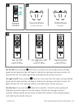
Page 20: ...te it was in prior to the module being turned on The UV module comes with 3 ultra violet indicator lights so you know the UV light is on Auto Off Timer Feature This feature will automatically turn off the UV light after a fixed period of time Feature is off by default To enable disable Press and hold and for 4 seconds The fan will beep indicating the change Default time 45 minutes Duration can be ...

Page 21: ...ndicate the message has been received All lights will turn off This will bring all fans controlled by the remote into sync Fan Direction Press and hold button for 4 seconds The LED on the remote will flash green and all connected fans will beep to indicate the message has been received All fans will be set to summer mode CCW rotation This will bring all fans controlled by the remote into sync 7 7A...

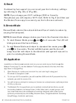
Page 22: ...eatures such as Adaptive Learning Integrate with smart home systems you already own including Amazon Alexa Google Assistant Samsung SmartThings Control 4 and more If advised by fan support you can reset your fan to factory settings by referring to Fig 8A or Fig 8B NOTE If you change your Wi Fi settings SSID or Security Passphrase you will require a Wi Fi reset Refer to Fig 8 and then use the Moder...

Page 23: ...ess and hold buttons for 10 seconds until the fan emits 3 beeps indicating the reset Unpairing Disassociate a remote control from a fan receiver press and hold Season Toggle and Fan Up for 4 seconds For detailed Instructions and Smart Home Device Integration Scan and follow prompts for instruction options and Smart Fan FAQs 100 LV2 Fan Wi Fi Reset Press and hold the and for 6 seconds until LED bli...

Page 24: ... Downrod XF 24 24 Downrod XF 36 36 Downrod XF 48 48 Downrod XF 60 60 Downrod XF 72 72 Downrod 11 Accessories personalize your experience Bluetooth UV Remote Control ON OFF 6 fan speeds F RCUV WT White 12 Troubleshooting My Fan Will Not Start 1 Check main and branch circuit fuses or circuit breakers 2 Check line wire connections to fan and switch wire connections in the switch housings CAUTION Make...

Page 25: ...g against the fan s canopy 6 Make sure you have a cUL UL approved outlet box and it is installed correctly My Fan is Wobbling 1 Tighten the set screws in the downrod 2 Make sure your hanger ball assembly is locked into place in the hanger bracket 3 Tighten the hanger bracket screws to the outlet box 4 Make sure the fan blades are properly aligned and securely fastened to the motor housing assembly...

Page 26: ...phone s list of available WiFi networks 1 If your fan had been previously paired the Wi Fi radio will be off 2 To reset the Wi Fi press and hold the and buttons on the remote control for 6 seconds until the indicator LED flashes and the fan sounds two beeps indicating the command was successful The fan will start to broadcast it s SSID 3 The fan will beep and you will see its Wi Fi network availab...

Page 27: ...e fan is powered through a wall switch turn the switch off for 10 seconds and back on Alternately you can use the circuit breaker the fan is connected to by toggling it off for 10 seconds and back on What is Adaptive Learning Adaptive learning is an exclusive feature that allows your fan to learn your daily weekly habits and automatically recommend scheduled activity through the Modern Forms app T...

Page 28: ...trol However if you want additional controls for your fan or if you re replacing a control refer to the pairing and unpairing section of the instructions What is a Factory Reset Factory Reset is a restore of the fans original settings This can be achieved from the control or by pressing and holding the small button on the receiver until you hear three audible beeps or by holding down the fan toggl...

Page 29: ...from warranty are any 3rd party component which carries its own manufacturer s warranty Note Modern Forms product warranty applies only to purchases from authorized Modern Forms distributors THERE ARE NO WARRANTIES WHICH EXTEND BEYOND THE DESCRIPTION ON THE FACE HEREOF INCLUDING WARRANTIES OF MERCHANTABILITY AND FITNESS FOR A PARTICULAR PURPOSE The Bluetooth word mark and logos are registered trad...

Page 30: ...us Cette garantie ne s applique pas aux produits qui ont été modifiés mal installés mal manipulés ou mal utilisés Un avis de défaut par écrit doit être reçu par Modern Forms dans les cinq 5 ans à compter de la date d achat ou selon la période de temps indiquée par le matériel Sont exclus de la garantie tout composant tiers qui porte sa propre garantie du fabricant Remarque la garantie du produit M...

Page 31: ...FR D2102 Ultra Germicidal Smart Fan Instructions 31 ...

Page 32: ...modernforms com FR D2102 ...

Reviews: