4-522.4
12
oPeration
During the normal operation, if the flame is lost for about 15
seconds, the primary control will again “lockout” and must be
manually reset.
The fan and limit switch performs the dual function of operating
the circulating air fan and turning the burner off if an overheat
condition occurs. Such a condition would exist if insufficient
circulating air is driven across the heat exchanger or if the unit
is over-fired.
The motor for the circulating air fan has internal thermal
overload protection. If for any reason, the motor overheats,
the thermal protector will shut it off. The motor will re-start
automatically when it has cooled.
Prior to operation
Although this unit has been inspected and fire-tested at the
factory, the following procedures should be performed to assure
proper on-site operation:
1. Check fan clearance. 1/4 inch is allowed between fan blade
tip and venturi.
2. Check all electrical connections to be sure they are secure,
and in accordance with the wiring diagram.
3. Check firmness of unit suspension. Tighten all fasteners, if
necessary.
4. Inspect vent pipe for rigidity of mounting. Gate on
barometric draft control should operate freely.
5. Trace oil lines for closed shut-off valves or filter head valves.
Open valves as required.
6. Inspect oil supply in storage tank to assure there is
sufficient fuel.
7. Check piping components (filters, Oil safety valves, etc.) to
make sure they are installed in the proper relationship to the
direction of oil flow.
8. Check to assure good electrical contact between
transformer terminals and electrode buss bars.
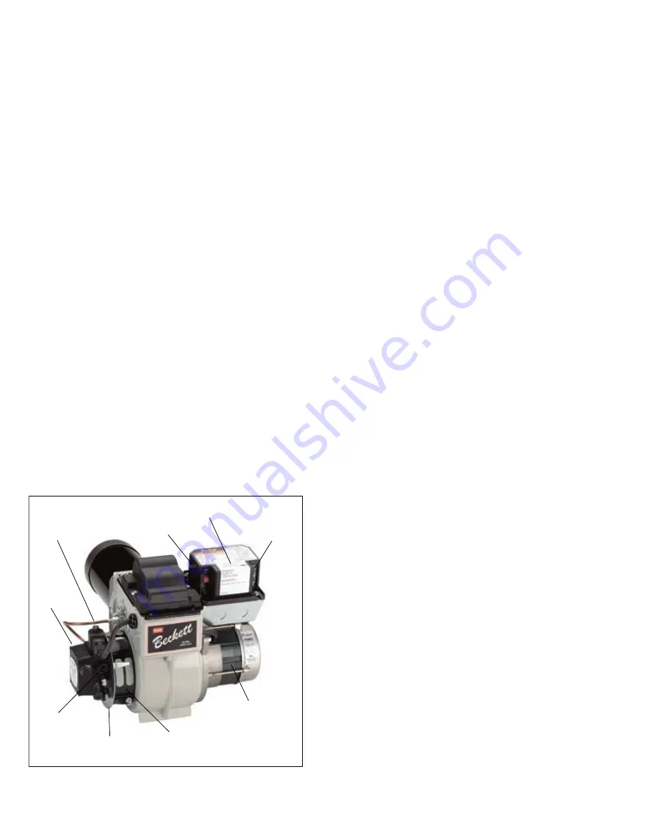
figure 12.1
Burner assembly with Webster fuel unit
initial start-up
1. Adjust room thermostat above room temperatures.
2. Open shut-off valves at tank and in oil supply line to the
burner.
3. Turn on power to the unit. If burner does not start
immediately, push reset buttons on burner motor and
primary control.
4. For units installed on a single pipe system, vent air from fuel
unit and oil supply lines immediately after the burner motor
starts. Vent air by opening bleeder valve on fuel unit until oil
appears clear (no foam), then close tightly. Ignition should
occur as soon as bleeder valve is closed.
If the air cannot be vented and ignition established within 15
seconds, the primary control will“lockout” and shut off the
burner. If this happens, wait several minutes to make sure
the heat exchanger is cool then push red reset button on
primary control. Repeat venting procedure until ignition has
been established.
For units installed on a two pipe system, venting of air from
oil lines is not necessary. However, ignition will not occur
until the air has been purged from the fuel unit and nozzle
line. This may take longer than 15 seconds and cause the
primary control to “lockout”. If this happens, wait several
minutes to make sure the heat exchanger is cool, then
push red reset button on primary control. Repeat venting
procedure until ignition has been established.
5. After ignition has been established, adjust the air bands
located on the left side of the burner to produce a #1 smoke
reading and allow the unit to run for approximately 10
minutes before making further adjustments. Then, adjust
the barometric draft control to produce a minus 0.02 inches
W.C. overfire draft. The draft reading must be taken in the
flue pipe between the barometric draft control and the unit
and as close to the unit as possible.
BLEEDER
VALVE
BURNER
FUEL UNIT
OIL
PRESSURE
ADJUSTING
SCREW
COMBUSTION
AIR SHUTTER
COMBUSTION
AIR BAND
IGNITION
TRANSFORMER
PRIMARY
CONTROL
RESET
THERMOSTAT
TERMINALS
BURNER
MOTOR


