4-522.4
13
oPeration
6. Shut unit off and connect a pressure gauge to the pressure
gauge port on the fuel unit. When the unit is turned on, the
pressure should be 130 +/- 2psi for POR100 and 145, 100
+/- 2psi for POR 185. If pressure adjustment is necessary,
adjust pressure with screwdriver or Allen wrench. See
Figure 7.2 and 8.1.
7. After the oil pressure is set, readjust the air bands to
produce just a trace of smoke which is slightly less than #1.
From the trace point, open the air bands to give 0 (zero)
smoke. A carbon dioxide (CO2) check at this smoke level
should read 11.5 to 12.5%. CO2 levels above 12.5% are not
recommended as sooting could occur as conditions and fuel
var y.
8. The fan and limit switch is factory set at a high limit
temperature of 210°F. Do not change this setting. It is
also factory set to turn on the fan at 120°F and turn it off
at 90°F. These settings may be changed by following the
control manufacturer’s instructions packed in the literature
envelope attached to the unit. Since the fan and limit control
is operated by a thermal switch, not the thermostat, residual
heat in the heat exchanger can cycle the fan on after the
thermostat has been satisfied.
9. Adjust the air deflector blades for desired heat distribution.
All horizontal blades should be kept open a minimum of 30°
as measured from vertical.
10. Run the unit through several cycles by raising and lowering
the thermostat setting to assure proper sequence of
operation.
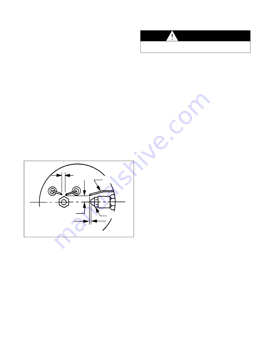
figure 13.1
electrode gap, Beckett Burner
service instructions
routine unit maintenance
Under average conditions, it is recommended that unit heaters
be serviced at least once a year and checked out prior to the
heating season. In excessively dirty atmospheres, service
should be performed more often.
1. Disconnect power supply to the unit before performing any
of following maintenance of inspection procedures.
2. Tighten fan guard and motor bracket. Check fan for proper
clearance, free rotation, and firm connection to motor shaft.
Clean fan blade with detergent or compressed air.
3. Fan motor is permanently lubricated for normal operation.
Under severe conditions, lubricate with non-detergent SAE
20 motor oil.
4. Routine cleaning of the unit casing and louvers is
recommended to remove dirt, grease, or corrosive
substances that may damage the finish. Rusted or corroded
spots on the louvers or casing should be sanded and
repainted. To remove, push louvers against retaining coil
spring and pull out at opposite tapered end.
5. With louvers removed inspect inside of heat exchanger with
a flash light through the flame inspection port. Check for
soot deposits, damaged fire pot, heat exchanger or burner
head.
6. If there is a heavy soot-coating inside heat exchanger, it
should be drawn out with a vacuum cleaner after removing
the front access panel. Care must be taken not to damage
the fire pot during the cleaning operation.
7. Replace fuel oil filter elements at unit heater and at
booster pump to prevent contamination of the fuel unit and
atomizing nozzle.
8. Check entire electrical system before every heating season.
9. Make sure gate on barometric draft control swings freely.
oil Burner service
The electric motor-driven burner assembly supplied with the
Modine oil-fired unit heaters lifts, pressures and atomizes a
continuous charge of fuel oil with a forced draft of combustion
air into the heat exchanger fire pot where it is ignited by
sparking electrodes. Burner components that will require
inspection and service include the burner motor, blower wheel
primary control, nozzle, nozzle, electrodes, and the fuel unit.
The burners utilize either a Honeywell, or White-Rodgers
primary control and cad cell and either a Webster or a Suntec
fuel unit. Refer to manufacturer’s instructions packed with each
unit.
CAUTION
Service procedures should only be performed by a qualified
oil serviceman.
5/16" ABOVE C L
NOZZLE
ELECTRODE
5/32" GAP
1/16"