background image

4-522.4

3. 

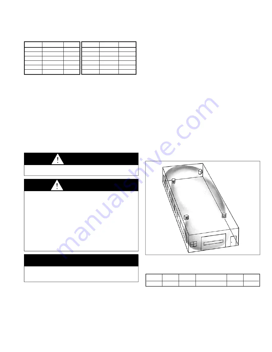
In multiple unit installations, arrange units so that each 
supports the air stream of the next unit, thus creating 
circulatory air movement in the area. See Figure 3.1. A large 
portion of the heated air should be directed toward the side 
of the building exposed to prevailing winds.

4. 

When locating units, it is important to consider that the 
exhaust vent piping must be connected to the outside 
atmosphere.

5. 

Be sure the structural support at the unit location site is 
adequate to support the weight of the unit. For proper 
operation the unit must be installed in a level horizontal 
position.

6. 

Do not install units in locations where the flue products 
can be drawn into the adjacent building openings such as 
windows, fresh air intakes, etc.

7. 

Be sure that the minimum clearances to combustible 
materials and recommended service clearances are 
maintained. Units are designed for installation on with the 
minimum clearances shown in Table 3.2.

8. 

Do not install units in locations where gas ignition system is 
exposed to water spray, rain, or dripping water.

9. 

Mounting Height (measured from bottom of unit) at which 
unit heaters are installed is critical. Refer to mounting height 
information and heat throw data on page 17 of this manual. 
The maximum mounting height for any unit is that height 
above which the unit will not deliver heated air to the floor.

figure 3.1
typical unit locations

table 3.2
combustible material and service clearances
all model sizes

3

general information

Install and wiring of these oil-fired unit heaters must conform to 
all applicable local codes, the National Electric Code, and NFPA 
No. 31 “Installation of Oil Burning Equipment” by the National Fire 
Protection Association. Installation of these unit heaters should 
only be performed by a qualified oil serviceman.

1.  These unit heaters are listed by Underwriters Laboratories, 

Inc., with components as furnished.

2.  Fuel oil grade No. 1 or 2, with a flash point not less than 100°F, 

is approved for these unit heaters as specified by (ASTM) 
D396-73 Standard Specification for Fuel Oils, or the Canadian 
Government Specification Board, 3-GP-28, (American Society 
for Testing and Materials).

si (metric) conversion factors / unit location


CAUTION

1. Do not locate units in tightly sealed rooms or small   
  compartments (commonly referred to as confined spaces)   
  without provisions for adequate combustion air and   
  venting. Combustion air must have access to the confined   
  space through a minimum of two permanent openings in   
  the enclosure, at least one near the bottom. They should   
  provide a free area of not less than one square inch per   
  1,000 BTU/Hr input rating of all units in the enclosure with   
  a minimum of 100 square inches for each opening,   
  whichever is greater.
2. When oil-fired unit heaters are to be installed in areas   
  having negative pressure (for example - a space with   
  exhaust fans) a power venter is recommended.

IMPORTANT

To prevent premature heat exchanger failure, do not locate 
ANY gas-fired appliances in areas where corrosive vapors (i.e. 
chlorinated, halogenated or acid) are present in the atmosphere.

 dANGER

Appliances must not be installed where they may be exposed 
to potentially explosive or flammable atmosphere.

si (metric) conversion factors

table 3.1

unit location

location recommendations

1. 

When location the furnace, consider general space and 
heating requirements, availability of gas and electrical 
supply, and proximity to vent locations.

2. 

Unit heaters should be located so they discharge air nearly 
parallel to exposed walls. Arrange units so they do not 
blow directly at occupants. Interference of air streams by 
columns, beams, partitions, or other obstructions should be 
avoided as much as possible.


Top  

Sides 

Back 

Front 

Bottom 

Flue


18” 

18” 

18” 

Unobstructed 

18” 

18”


 to convert multiply By to obtain


"W.C. 

0.24 

kPa


psig 

6.893 

kPa


°F 

(°F-32) x 0.555 

°C


inches 

25.4 

mm


feet 

0.305 

meters


CFM 

0.028 

m

3

/min

 to convert multiply By to obtain


CFH 

1.699 

m

3

/min


Btu/ft

3


0.0374 

mJ/m

3


pound 

0.453 

kg


Btu/hr 

0.000293 

kW/hr

  gallons 

3.785 

liters


psig 

27.7 

"W.C.

Summary of Contents for POR

Page 1: ...ry or death and could cause exposure to substances which have been determined by various state agencies to cause cancer birth defects or other reproductive harm read the installation operating and maintenance instructions thoroughly before installing or servicing this equipment FOR YOUR SAFETY WHat to do if you smell gas 1 open windows 2 do not try to light any appliance 3 do not touch any electri...

Page 2: ...of not less than one square inch per 1 000 BTU Hr input rating of all units in the enclosure with a minimum of 100 square inches for each opening whichever is greater IMPORTANT 1 To prevent premature heat exchanger failure do not locate ANY oil fired appliances in areas where corrosive vapors i e chlorinated halogenated or acid are present in the atmosphere 2 To check most of the Possible Remedies...

Page 3: ...ade No 1 or 2 with a flash point not less than 100 F is approved for these unit heaters as specified by ASTM D396 73 Standard Specification for Fuel Oils or the Canadian Government Specification Board 3 GP 28 American Society for Testing and Materials si metric conversion factors unit location CAUTION 1 Do not locate units in tightly sealed rooms or small compartments commonly referred to as confi...

Page 4: ...r suspension methods note A pipe hanger adapter kit shown in figure 4 1 is available as an accessory from Modine or can be self fabricated Kit consists of two drilled 3 4 I P S pipe caps and two 1 2 13 x 1 3 4 capscrews to facilitate threaded pipe suspension Two kits are required for mounting each unit figure 4 1 suspension methods venting 1 To dispose of flue gasses all oil fired heaters must be ...

Page 5: ...r in at least 1 2 inch thin wall or flexible metal conduit thermostat Wiring The proper wiring for a single thermostat for each unit heater is shown in Figure 6 1 The multiple unit wiring diagram shown in Figure 6 2 illustrates typical wiring and connections used with a centralized oil distribution system for multiple unit installations This diagram is provided as a reference only and is not inten...

Page 6: ...NG PRIMARY CONTROL This diagram is provided for reference only System operation and compliance with local codes is the responsibility of the installer Note All wiring shown as dashed lines is field wiring FIELD WIRING JUNCTION BOX ON HEATER 115V 60HZ 1Ø GROUND IN J BOX FUSED DISCONNECT SWITCH BY OTHERS PRESSURE SWITCH ACCESSORY BURNER MOTOR LOW VOLTAGE T STAT BY OTHERS UNIT 1 T T BURNER HOUSING PR...

Page 7: ...ipe systems See Figure 8 1 If more than one unit is piped to the same tank separate suction oil lines must be installed for each unit A single common line however can be piped in series for fuel oil return one Pipe system The fuel units supplied contain an internal by pass and are shipped from the factory with the by pass plug in place for one pipe installations only supply line connected to fuel ...

Page 8: ...ceed 3 PSIG For multiple unit systems as shown in Figures 9 1 and 9 2 install a generous capacity oil filter in the inlet line to booster pump suction line Refer to Figure 6 2 for a typical wiring diagram for multiple unit installations oil tanks To provide for a safe and continuous fuel supply the tanks and piping to the unit heaters must be installed in accordance with state and local codes and ...

Page 9: ...4 522 4 9 installation figure 9 1 typical loop system for multiple units figure 9 2 typical Pressurized supply system for multiple units ...

Page 10: ...fuel filter oil safety valve osv The Oil safety valve can be installed in any position Preferred position is cover up The IN port is connected to the supply line the OUT port to the burner line Do not install backwards The Oil safety valve is opened by a slight vacuum appearing at the outlet of the Oil safety valve generated by the burner fuel unit Failure to observe the above caution may result i...

Page 11: ...When the fan and limit switch detects the proper temperature it will turn on the circulating air fan The time it takes before the circulating air fan turns on after the burner is started is a function of the temperature setting on the fan and limit switch When the thermostat is satisfied the primary control will shut off the burner The circulating air fan will shut off when the fan and limit switc...

Page 12: ... temperatures 2 Open shut off valves at tank and in oil supply line to the burner 3 Turn on power to the unit If burner does not start immediately push reset buttons on burner motor and primary control 4 For units installed on a single pipe system vent air from fuel unit and oil supply lines immediately after the burner motor starts Vent air by opening bleeder valve on fuel unit until oil appears ...

Page 13: ...ction procedures 2 Tighten fan guard and motor bracket Check fan for proper clearance free rotation and firm connection to motor shaft Clean fan blade with detergent or compressed air 3 Fan motor is permanently lubricated for normal operation Under severe conditions lubricate with non detergent SAE 20 motor oil 4 Routine cleaning of the unit casing and louvers is recommended to remove dirt grease ...

Page 14: ... for an accumulation of dirt or soot Clean if necessary with a soft cloth 7 Lubricate burner motor with a few drops of non detergent oil at both motor oil holes twice each year on units that are not permanently lubricated with sealed bearings Burner adjustments It is recommended that a combustion check be made on the burner each year or whenever replacing a nozzle This will help assure efficient c...

Page 15: ...content Zero the CO2 analyzer and insert probe into flue pipe and draw sample of the flue gas into analyzer The concentration of CO2 should be 11 5 to 12 5 CO2 levels above 12 5 are not recommended as sooting could occur as conditions and fuel vary at zero smoke G Conclude testing by reading stack temperature and subtract room temperature to get the net stack temperature Using this figure and the ...

Page 16: ... running and should not drop to less than 80 PSI and hold there after the burner is shut off If the pressure drops to zero the fuel unit should be replaced fire Pot service The ceramic fiber fire pot will seldom if ever require replacement unless it is accidentally damaged during a heat exchanger cleaning operation To replace take off the front access panel and remove all fire pot pieces Carefully...

Page 17: ...put input output cfm delivery temp max mtg Heat model Btu Hr gPH Btu Hr 70 f fPm rise f Ht ft throw ft Por 100 119 000 85 100 000 1890 460 49 12 39 Por 145 175 000 1 25 145 000 2400 580 56 13 5 50 Por 185 231 000 1 65 185 000 3200 740 54 12 51 Deflector blades pitch 45 toward the floor Heated air Mounting heights measured from floor to bottom of unit The maximum mounting height is that height abov...

Page 18: ...el pump service diagnosis Problem d Burner operates but fan does not operate 1 Fan motor failure 1 a Check for loose electrical connections Check wiring with diagram on rear of heater b Repair or replace burned out or defective motor c Voltage too high or too low Check voltage with voltmeter 2 Loose fan 2 Tighten fan set screw 3 Defective fan switch in fan limit control 3 Replace entire control 4 ...

Page 19: ...Make sure return line is below oil level in tank 7 A single pipe system that becomes air bound 7 Loosen gauge port plug or easy flow valve and bleed oil for 15 seconds after foam is gone in bleed hose Check intake line fittings for tightness Check all pump plugs for tightness 8 Slipping or broken coupling 8 Tighten or replace coupling 9 Rotation of motor and fuel unit is not the same 9 Install fue...

Page 20: ...D HEREIN SHALL BE LIMITED TO ONE YEAR FROM DATE OF SHIPMENT FROM SELLER Heat exchanger condensers for all seller s products except non separated combustion gas fired unit Heaters and infrared Heaters all Burners except infrared Heaters and sheet metal for all seller s products BUYER S REMEDY FOR BREACH OF WARRANTY EXCLUSIVE OF ALL OTHER REMEDIES PROVIDED BY LAW IS LIMITED TO REPAIR OR REPLACEMENT ...

Reviews: