background image

4-522.4

4

installation

combustion air requirements

For complete combustion, 14-1/2 lbs. of air is required for 
each pound of No. 2 fuel oil. Lack of combustion air can cause 
erratic burner operation, noisy combustion, fuel odors and soot 
deposits on heat exchanger walls resulting in lowered efficiency 
and high fuel consumption.

Units installed in tightly sealed buildings or confined spaces 
must be provided with two permanent openings, one near 
the top of the confined space and one near the bottom. Each 
opening should have a free area of not less than one square 
inch per 1,000 BTU per hour of the total input rating of all units 
in the enclosure with a minimum of 100 square inches for each 
opening, whichever is greater, freely communicating with interior 
areas having, in turn adequate infiltration from the outside.

For further details on supplying combustion air to a confined 
(tightly sealed) space or unconfined space, see the National 
Fuel Gas Code ANSI Z223.1 of CAN/CGA B149.1 or .2 
Installation Code, latest edition.

confined of unconfined spaces

The National Fuel Gas Code defines an “unconfined space” as 
a space whose volume is greater than 50 cubic feet per 1000 
Btu/Hr input of the installed appliance(s). A confined space 
is 50 cubic feet or less per 1000 Btu/Hr input of the installed 
appliance(s).

unit suspension

1. 

Be sure the means of suspension is adequate to support 
the weight of the unit (see Table 17.1 for unit weights).

2. 

For proper operation, the unit must be installed in a level 
horizontal position.

3. 

Clearances to combustibles as previously specified must be 
strictly maintained.

4. 

It is recommended that adequate service access in access 
of 18 inches be provided for the burner and fan limit switch.

5. 

Do not install unit heater above the maximum mounting 
height shown in Table 17.2.

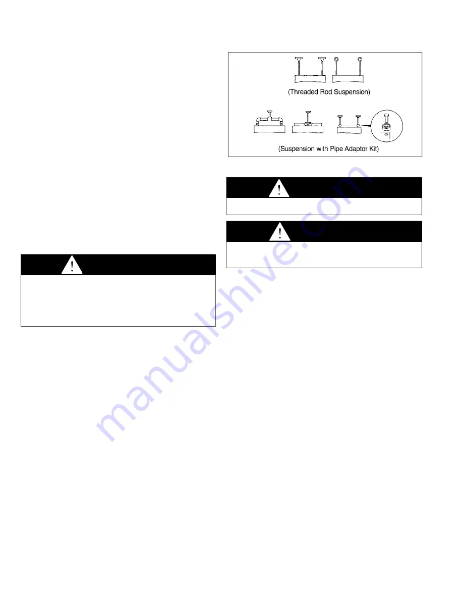
Four tapped holes (1/2" - 13) in the top of the unit are provided 
for unit heater suspension. Suspension can be made with 
threaded rods, pipes, or ceiling hanger brackets furnished by 
others. See Figure 17.1 for hanger hole locations and Figure 4.1 
for suspension methods.

note: A pipe hanger adapter kit, shown in figure 4.1 is 
available as an accessory from Modine, or can be self-
fabricated. Kit consists of two drilled 3/4" I.P.S. pipe caps and 
two 1/2" - 13 x 1-3/4" capscrews to facilitate threaded-pipe 
suspension. Two kits are required for mounting each unit.

figure 4.1 - suspension methods 

venting

1.  To dispose of flue gasses, all oil-fired heaters must be 

vented per NFPA No. 31 “Installation of Oil Burning 
Equipment” and all local codes.

2.  Do not install chimney connector closer than 18 inches 

to combustible materials in any direction. Where chimney 
connector passes through a wall or partition, a metal 
ventilated thimble not less than 12 inches larger in diameter 
than the connector must be used.

3.  All Modine oil-fired heaters have an 8 inch vent connection. 

Never use a chimney connector smaller than 8 inches, 
except a 7 inch adapter may be used on Model POR100 to 
accomodate a 7 inch vent.

4.  Install a barometric draft control the same size and on 

the vent pipe as close to the unit as possible. Installing a 
barometric draft control is essential for proper operation 
of the unit. Excessive over fire draft can cause unburned 
fuel to accumulate in the stack creating a potentially 
explosive condition. To install barometric draft control, refer 
to instructions furnished by draft control manufacturer. The 
air flow opening of the barometric draft control should face 
the front of the unit heater or away from air currents in the 
vicinity of the heater.

THE BAROMETRIC DRAFT CONTROL MUST BE ADJUSTED 
TO PROVIDE MINUS 0.02 INCHES W.C. (WATER COLUMN) 
OVERFIRE DRAFT AS MEASURED BETWEEN THE DRAFT 
CONTROL AND THE UNIT AND AS CLOSE TO THE UNIT AS 
POSSIBLE.


CAUTION

1.  Do not install units below 7 feet, measured from the 

bottom of the unit to the floor, unless properly guarded to 
provide protection from moving parts.

2.  Do not install unit heater or vent pipe closer than 18 

inches to combustible materials in any direction, except 
the front of the unit heater, which must be unobstructed.


WARNING

Oil-fired heating equipment must be vented - do not operate 

unvented. 


CAUTION

A barometric draft control must be installed on each unit 
heater, in the same space as the unit heater and as close to 
the unit as possible. 

Summary of Contents for POR

Page 1: ...ry or death and could cause exposure to substances which have been determined by various state agencies to cause cancer birth defects or other reproductive harm read the installation operating and maintenance instructions thoroughly before installing or servicing this equipment FOR YOUR SAFETY WHat to do if you smell gas 1 open windows 2 do not try to light any appliance 3 do not touch any electri...

Page 2: ...of not less than one square inch per 1 000 BTU Hr input rating of all units in the enclosure with a minimum of 100 square inches for each opening whichever is greater IMPORTANT 1 To prevent premature heat exchanger failure do not locate ANY oil fired appliances in areas where corrosive vapors i e chlorinated halogenated or acid are present in the atmosphere 2 To check most of the Possible Remedies...

Page 3: ...ade No 1 or 2 with a flash point not less than 100 F is approved for these unit heaters as specified by ASTM D396 73 Standard Specification for Fuel Oils or the Canadian Government Specification Board 3 GP 28 American Society for Testing and Materials si metric conversion factors unit location CAUTION 1 Do not locate units in tightly sealed rooms or small compartments commonly referred to as confi...

Page 4: ...r suspension methods note A pipe hanger adapter kit shown in figure 4 1 is available as an accessory from Modine or can be self fabricated Kit consists of two drilled 3 4 I P S pipe caps and two 1 2 13 x 1 3 4 capscrews to facilitate threaded pipe suspension Two kits are required for mounting each unit figure 4 1 suspension methods venting 1 To dispose of flue gasses all oil fired heaters must be ...

Page 5: ...r in at least 1 2 inch thin wall or flexible metal conduit thermostat Wiring The proper wiring for a single thermostat for each unit heater is shown in Figure 6 1 The multiple unit wiring diagram shown in Figure 6 2 illustrates typical wiring and connections used with a centralized oil distribution system for multiple unit installations This diagram is provided as a reference only and is not inten...

Page 6: ...NG PRIMARY CONTROL This diagram is provided for reference only System operation and compliance with local codes is the responsibility of the installer Note All wiring shown as dashed lines is field wiring FIELD WIRING JUNCTION BOX ON HEATER 115V 60HZ 1Ø GROUND IN J BOX FUSED DISCONNECT SWITCH BY OTHERS PRESSURE SWITCH ACCESSORY BURNER MOTOR LOW VOLTAGE T STAT BY OTHERS UNIT 1 T T BURNER HOUSING PR...

Page 7: ...ipe systems See Figure 8 1 If more than one unit is piped to the same tank separate suction oil lines must be installed for each unit A single common line however can be piped in series for fuel oil return one Pipe system The fuel units supplied contain an internal by pass and are shipped from the factory with the by pass plug in place for one pipe installations only supply line connected to fuel ...

Page 8: ...ceed 3 PSIG For multiple unit systems as shown in Figures 9 1 and 9 2 install a generous capacity oil filter in the inlet line to booster pump suction line Refer to Figure 6 2 for a typical wiring diagram for multiple unit installations oil tanks To provide for a safe and continuous fuel supply the tanks and piping to the unit heaters must be installed in accordance with state and local codes and ...

Page 9: ...4 522 4 9 installation figure 9 1 typical loop system for multiple units figure 9 2 typical Pressurized supply system for multiple units ...

Page 10: ...fuel filter oil safety valve osv The Oil safety valve can be installed in any position Preferred position is cover up The IN port is connected to the supply line the OUT port to the burner line Do not install backwards The Oil safety valve is opened by a slight vacuum appearing at the outlet of the Oil safety valve generated by the burner fuel unit Failure to observe the above caution may result i...

Page 11: ...When the fan and limit switch detects the proper temperature it will turn on the circulating air fan The time it takes before the circulating air fan turns on after the burner is started is a function of the temperature setting on the fan and limit switch When the thermostat is satisfied the primary control will shut off the burner The circulating air fan will shut off when the fan and limit switc...

Page 12: ... temperatures 2 Open shut off valves at tank and in oil supply line to the burner 3 Turn on power to the unit If burner does not start immediately push reset buttons on burner motor and primary control 4 For units installed on a single pipe system vent air from fuel unit and oil supply lines immediately after the burner motor starts Vent air by opening bleeder valve on fuel unit until oil appears ...

Page 13: ...ction procedures 2 Tighten fan guard and motor bracket Check fan for proper clearance free rotation and firm connection to motor shaft Clean fan blade with detergent or compressed air 3 Fan motor is permanently lubricated for normal operation Under severe conditions lubricate with non detergent SAE 20 motor oil 4 Routine cleaning of the unit casing and louvers is recommended to remove dirt grease ...

Page 14: ... for an accumulation of dirt or soot Clean if necessary with a soft cloth 7 Lubricate burner motor with a few drops of non detergent oil at both motor oil holes twice each year on units that are not permanently lubricated with sealed bearings Burner adjustments It is recommended that a combustion check be made on the burner each year or whenever replacing a nozzle This will help assure efficient c...

Page 15: ...content Zero the CO2 analyzer and insert probe into flue pipe and draw sample of the flue gas into analyzer The concentration of CO2 should be 11 5 to 12 5 CO2 levels above 12 5 are not recommended as sooting could occur as conditions and fuel vary at zero smoke G Conclude testing by reading stack temperature and subtract room temperature to get the net stack temperature Using this figure and the ...

Page 16: ... running and should not drop to less than 80 PSI and hold there after the burner is shut off If the pressure drops to zero the fuel unit should be replaced fire Pot service The ceramic fiber fire pot will seldom if ever require replacement unless it is accidentally damaged during a heat exchanger cleaning operation To replace take off the front access panel and remove all fire pot pieces Carefully...

Page 17: ...put input output cfm delivery temp max mtg Heat model Btu Hr gPH Btu Hr 70 f fPm rise f Ht ft throw ft Por 100 119 000 85 100 000 1890 460 49 12 39 Por 145 175 000 1 25 145 000 2400 580 56 13 5 50 Por 185 231 000 1 65 185 000 3200 740 54 12 51 Deflector blades pitch 45 toward the floor Heated air Mounting heights measured from floor to bottom of unit The maximum mounting height is that height abov...

Page 18: ...el pump service diagnosis Problem d Burner operates but fan does not operate 1 Fan motor failure 1 a Check for loose electrical connections Check wiring with diagram on rear of heater b Repair or replace burned out or defective motor c Voltage too high or too low Check voltage with voltmeter 2 Loose fan 2 Tighten fan set screw 3 Defective fan switch in fan limit control 3 Replace entire control 4 ...

Page 19: ...Make sure return line is below oil level in tank 7 A single pipe system that becomes air bound 7 Loosen gauge port plug or easy flow valve and bleed oil for 15 seconds after foam is gone in bleed hose Check intake line fittings for tightness Check all pump plugs for tightness 8 Slipping or broken coupling 8 Tighten or replace coupling 9 Rotation of motor and fuel unit is not the same 9 Install fue...

Page 20: ...D HEREIN SHALL BE LIMITED TO ONE YEAR FROM DATE OF SHIPMENT FROM SELLER Heat exchanger condensers for all seller s products except non separated combustion gas fired unit Heaters and infrared Heaters all Burners except infrared Heaters and sheet metal for all seller s products BUYER S REMEDY FOR BREACH OF WARRANTY EXCLUSIVE OF ALL OTHER REMEDIES PROVIDED BY LAW IS LIMITED TO REPAIR OR REPLACEMENT ...

Reviews: