01/08 AWB2190-1430GB
Setting the functions with DIP
switches (RA-SP-HE…)
111
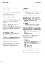
Activate phase reversal switch (pole 7)
Table 27: Phase reversal and reversing function
Configuring stop behaviour of RA-SP-HE… (pole 8)
RA-SP does not need an external 24 V DC control voltage.
RA-SP-HE… allows a controlled power-off with the second ramp
when the external 24 V DC fails. This function requires the
24 V DC to be supplied through the user-assembled M12 plug.
For parameterizing the second deceleration time with parameter
number PNU A93
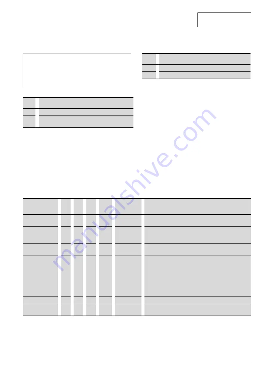
Reading diagnostic status through AS-Interface® parameter channel with RA-SP-HE…
To be able to read out the diagnostic status (DIP pole 2 = 1,
a
table 24) the PLC with WRITE P must send the parameter bit
combination 111. The RA-SP-HE… responds with the diagnostic
status (
table 28). If no diagnostic data is available, the RA-SP-
HE… returns the parameter bit combination 111.
If two or more diagnostic messages apply at the same time, the
message with the highest priority is displayed until the fault that
triggered the diagnosis has been rectified and the Reset command
has been issued. Then the diagnostic message with the next
highest priority is displayed. The messages are listed in order of
their priority.
The highest-priority message is at the top of the list.
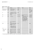
Table 28: Diagnostic status
j
Danger!
Safety risk! The jumper positions and the setting of DIP
switch pole 7 must be changed only by trained persons
and only in accordance with this manual. Incorrect
settings will cancel the reversing starter’s interlock or
reverse the operating direction.
Pole 7
Configuration
0
Reversing starter (default)
1
Reversing starters and phases L1 and L3 reversed (phase
reversal)
Pole 8
Configuration
0
No response to external 24 V DC control voltage (default)
1
Power-off with second ramp when external 24 V DC fails
Diagnostic status
P1
P2
P3
P4
Group error
at DI1
Explanation/parameter number
Device defective
0
0
1
0/1
1
Processor defective (E11 and E22)
EEPROM fault (E08)
Overload tripping
0
1
0
0/1
1
Overcurrent in output stage (E01, E02, E03, E04)
Overload (E05)
Overvoltage in regenerative mode (E07)
Thermistor tripping
0
1
1
0/1
1 (only when
DIP pole 1 = 0)
Tripping through excessive resistance in thermistor sensor circuit
No special
diagnostics message
1
1
1
0/1
1
Possible causes:
• Undervoltage (E09)
• Unattended start protection tripped (E13)
• Earth-fault, (E14)
• Mains overvoltage (E15)
• Overtemperature (E21)
• Power plug removed
• Overload/short-circuit I3/I4
Manual mode
1
0
0
0/1
0
Key-switch in MANUAL (HAND) position
Load signal
1
0
1
0/1
0
Threshold for overload alarm signal (value adjustable through
parameter C41)
Summary of Contents for Rapid Link
Page 10: ...01 08 AWB2190 1430GB 6 ...
Page 40: ...01 08 AWB2190 1430GB 36 ...
Page 48: ...01 08 AWB2190 1430GB 44 ...
Page 70: ...01 08 AWB2190 1430GB 66 ...
Page 146: ...01 08 AWB2190 1430GB 142 ...
Page 162: ...01 08 AWB2190 1430GB 158 ...

