Head station RA-IN
01/08 AWB2190-14
3
0GB
28
Installation
Mounting position
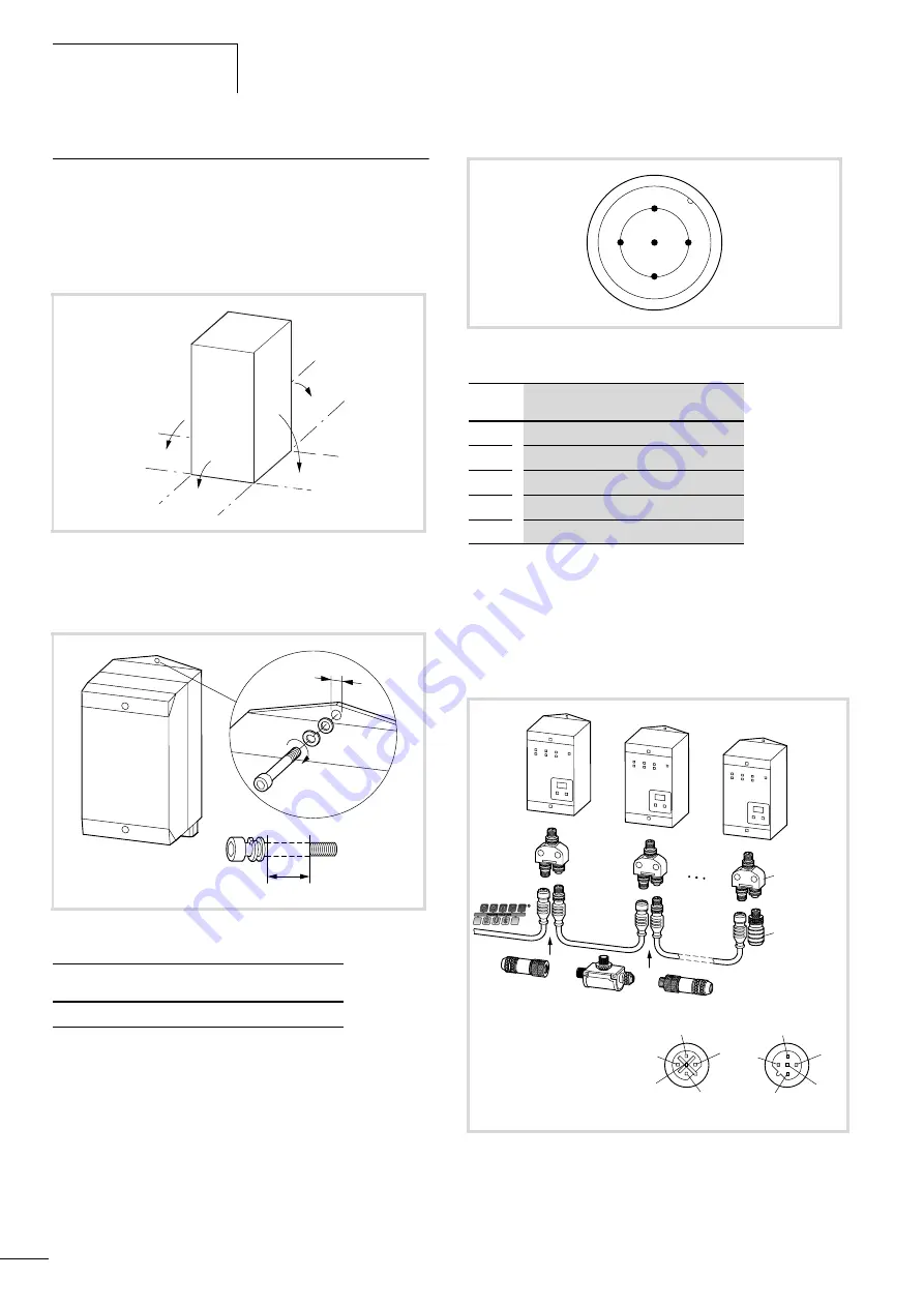
The device is preferably installed vertically but can also be fitted in
any other positions.
Mounting
PROFIBUS-DP interface
The PROFIBUS-DP interface is implemented as an M12 socket as
specified in PROFIBUS guideline “Interconnection Technology”.
For interference-free operation of PROFIBUS, the bus must be
terminated with an active bus termination in the form of a bus
termination plug. Spur lines are permissible only at baud rates
below
F
1.5 MBit/s. For higher baud rates, the T- or Y-connector
must be connected directly to the RA-IN without spur line. The
connectors have the additional advantage that they allow
replacement of the RA-IN unit without interrupting the bus.
Figure 26: Mounting position
Figure 27: Mounting
o
[mm]
Thread
Torque [Nm]
5.5
M5
3
F
90
F
90
F
90
F
90
o
5
Figure 28: M12 connector for RS 485 in IP65/67
pin
identification
1
VP
2
RxD/TxD-N (data cable A, green)
3
DGND
4
RxD/TxD-P (data cable B, red)
5
screen
M12
x
1
REVERSED
KEYED
1. nc
2. green
3
. nc
4. red
5. shield
Figure 29: Connection to PROFIBUS-DP
2
3
4
5
1
RA-IN-XY-DP
RA-IN-XTR-DP
3
2
4
5
1
1
2
4
5
3
Summary of Contents for Rapid Link
Page 10: ...01 08 AWB2190 1430GB 6 ...
Page 40: ...01 08 AWB2190 1430GB 36 ...
Page 48: ...01 08 AWB2190 1430GB 44 ...
Page 70: ...01 08 AWB2190 1430GB 66 ...
Page 146: ...01 08 AWB2190 1430GB 142 ...
Page 162: ...01 08 AWB2190 1430GB 158 ...


