01/08 AWB2190-1430GB
Engineering
13
Power bus
The power bus supplies the Rapid Link function modules with main
and auxiliary power. Plug-in tap-off points can be quickly and
safely connected at any point along the bus. The power bus can
consist either of a flexible busbar (flat cable) or standard round
cables:
Incoming supply 400 V AC
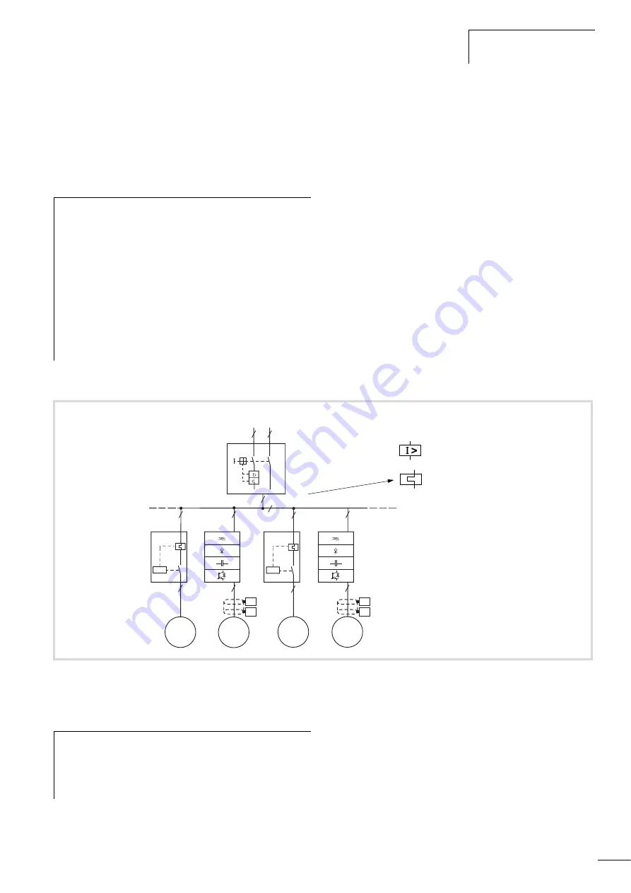
The power sections are supplied through disconnect control unit
RA-DI (see illustration below) with:
•
I
e
F
20 A/400 V at 2.5 mm
2
•
I
e
F
25 A/400 V at 4 mm
2
.
Round cables up to 6 mm
2
can be used to feed power to
disconnect control unit RA-DI.
• The disconnect control unit RA-DI protects the cable from
overload.
• It also provides short-circuit protection for the cable and for all
connected motor control units RA-MO.
The combination of RA-DI and RA-MO fulfills the requirements of
IEC/EN 60947-4-1 as starter with type “1” coordination. That
means that the contactor’s contacts in the RA-MO are allowed to
weld in the event of a short-circuit in the motor terminal strip or
the motor supply cable. This arrangement also conforms to IEE
wiring regulations.
The affected RA-MO motor control unit must be replaced after a
short-circuit!
When you configure a power bus with a disconnect control unit,
observe the following:
• Even in the event of a single-pole short-circuit at the line end,
the short-circuit current must exceed 150 A (250 A). This value
is a main factor in determining the length of the power bus.
• The total current of all running and simultaneously starting
motors must not exceed 110 A (170 A).
• The incoming circuit-breaker RA-DI (or PKZ2-ZM25-8) can
switch on the following number of speed controllers RA-SP
without the short-circuit release being tripped by the RA-SP:
– 10 to 15 (20 to 25) RA-SP...075... or
– 5 to 8 (10 to 13) RA-SP...1K1... or
– 3 ti 5 ( 7 to 9) RA-SP…2K2…
j
Warning!
• Rapid Link must be operated only on 400V-three-phase
systems with earthed star point and separate N and PE
conductors (TN-S network). It must not be operated
unearthed.
• All devices am connected to the power and data bus
must also meet the requirements for safe isolation
according to IEC/EN 60947-1 Annex N or IEC/
EN 60950. The24 V DC power supply unit must be
earthed on the secondary side. The 30 V DC PSU for
the AS-Interface
®
-/RA-IN-power supply must meet the
safe isolation requirements according to SELV.
Figure 6:
Example arrangement, Rapid Link system with RA-DI, RA-MO and RA-SP
e
M
3
h
1.5 mm
2
2.5 mm
2
/ 4 mm
2
3
AC 400 V
h
,
50/60 Hz
24 V
H
RA-DI
Q1
M
3
h
e
e
M
3
h
1.5 mm
2
1.5 mm
2
RA-MO
RA-SP
RA-MO
M
3
h
e
Motor Control Un
i
ts RA-MO,
Spee
d
Control Un
i
ts RA-SP
D
i
sconnect
Control Un
i
t RA-DI
F
6 mm
2
1.5 mm
2
1.5 mm
2
1.5 mm
2
1.5 mm
2
RA-SP
1.5 mm
2
PES
PES
PES
PES
⎧ ⎨ ⎩
F
20 A at 2,5 mm
2
F
25 A at 4 mm
2
= 130 A – 210 A
h
The short-circuit release of the RA-DI is factory set top the
lowest setting of 130 A. The values in brackets in the list
below apply to the maximum setting of 210 A. The
configuration of the short-circuit release is described on
page 39.
Summary of Contents for Rapid Link
Page 10: ...01 08 AWB2190 1430GB 6 ...
Page 40: ...01 08 AWB2190 1430GB 36 ...
Page 48: ...01 08 AWB2190 1430GB 44 ...
Page 70: ...01 08 AWB2190 1430GB 66 ...
Page 146: ...01 08 AWB2190 1430GB 142 ...
Page 162: ...01 08 AWB2190 1430GB 158 ...


