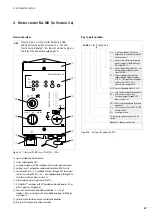
Head station RA-IN
01/08 AWB2190-1430GB
32
Change to engineering mode
X
If the yellow prj mode LED is not lit, press the Mode key for
about five seconds.
The yellow prj mode LED is now lit and the device is in engineering
mode.
Connect the first slave with address 0
X
Connect the slave.
The green ASi active LED lights up. The display shows 0, which
indicates that the AS-Interface
®
master has detected the slave.
Change the slave address to 1
X
Press the Set key several times to select address 1. The next free
address is shown with each press.
X
Press the key until the display shows “1”.
X
Now press and hold the Set key for about five seconds until the
displayed address 1 flashes.
Apply the address to the slave by pressing the Set key again briefly.
RA-IN recognises the slave with address 1 and displays it.
Connect a second slave with address 0 and assigning
address 2
X
Connect a further AS-Interface
®
slave to the AS-Interface
®
line.
To assign addresse to further AS-Interface
®
slaves, repeat the
above procedure. The display now cycles through the addresses of
the detected slaves.
Change to protected operation mode and save the AS-
Interface
®
configuration
X
Exit engineering mode by pressing the Mode key for about five
seconds until the prj mode LED goes out.
Configuration of the AS-Interface
®
master is now completed. You
can now take the higher-level fieldbus into operation. The
gateway remains in offline phase (display dark, ASi active LED off)
until the higher-level fieldbus is operating correctly.
Indicating elements
Display and control unit
Digital display
In the basic state in engineering mode, the addresses of all
detected AS-Interface
®
slaves are displayed at a rate of two per
second. A blank display indicates a blank LDS (
l
ist of
d
etected
s
laves), i.e. no slaves were detected.
In the basic state in protected operation mode the display is blank
or shows an incorrectly assigned address (
“Configuration errors in protected operation mode”, page 30).
During manual address programming the slave address display
has a different meaning (
section “Addressing AS-Interface
slaves in engineering mode” on page 30 and section “Addressing
AS-Interface
slaves with configuration errors” on page 31).
The displayed values have the following meanings:
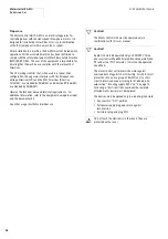
h
Caution!
For error messages not relating to incorrect assignments
in the AS-Interface
®
circuit, error codes
f
50 are
displayed, which lie outside the value range for slave
addresses. These codes are described in section “Digital
display”, page 32.
programming
button
meaning
mode
Changeover between engineering mode and
protected operation mode, and saving the current
AS-Interface
®
configuration as target
configuration
set
Selection and setting of addresses for
AS-Interface
®
slaves
h
All displayed values above 31 (the highest possible slave
address) are status or error messages from the device.
Summary of Contents for Rapid Link
Page 10: ...01 08 AWB2190 1430GB 6 ...
Page 40: ...01 08 AWB2190 1430GB 36 ...
Page 48: ...01 08 AWB2190 1430GB 44 ...
Page 70: ...01 08 AWB2190 1430GB 66 ...
Page 146: ...01 08 AWB2190 1430GB 142 ...
Page 162: ...01 08 AWB2190 1430GB 158 ...


