7.3 XSMA breakout board
45
7.3
XSMA breakout board
The
XSMA
breakout board (Figure 7.3) is an optional additional com-
ponent that provides
SMA
connectors for each of the digital
I/O
lines
of both the
DB15
connector (
§
7.1) and the high-speed bus (
§
7.2).
The pins of the high-speed bus have matched track-lengths, to en-
sure consistent propagation delay for applications using advanced
table mode.
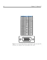
Figure 7.3:
XSMA
digital
I/O
breakout board, providing
SMA
connectors
for the
DB15
connector (left) and high-speed digital connector (right).
The flat-flex cable (
FFC
) carrying the high-speed digital
I/O
signals
can be inserted in either orientation, with contacts facing up or down.
Each pin of the high-speed bus has two labels, corresponding to the
purpose of the pin given the cable orientation.
If the orientation is the same within the
ARF/XRF
and the
XSMA
board,
the second set of labels apply, whereas if the cable is crossed-over,
the first set apply. Second-generation breakout boards include
LED
indicators
labelled
“Top”
and
“Bottom”
that
identify
which
set
of
labels to use.
The board dimensions are 172x70mm (first generation) or 172x85mm
(second generation).
Summary of Contents for ARF021
Page 1: ...Agile RF Synthesizer AOM driver ARF021 ARF421 XRF021 XRF421 Version 1 5 0 Rev 6 ...
Page 4: ...ii ...
Page 10: ...viii Contents ...
Page 26: ...16 Chapter 3 Communications ...
Page 44: ...34 Chapter 5 External modulation ...
Page 50: ...40 Chapter 6 PID stabilisation ...
Page 64: ...54 Chapter 7 Digital I O ...
Page 100: ...90 Chapter 9 Advanced table mode XRF ...
Page 128: ...118 Appendix C Command language ...
Page 133: ......

