background image

MoJack 750XT Lift

19

Maintenance Schedule

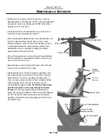
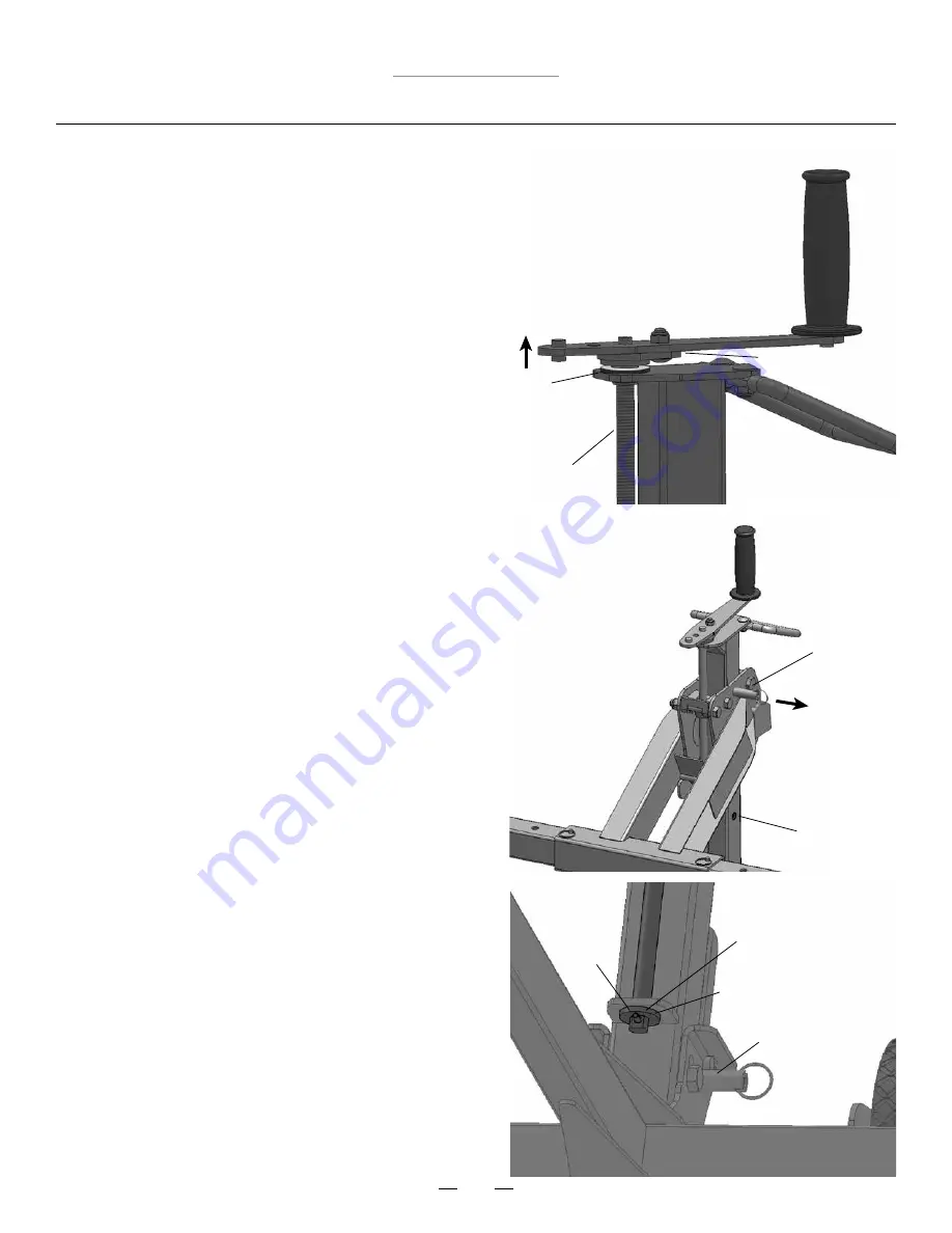
• Before each use, always check for any worn, loose or  
  damaged parts on the MoJack 750XT. If any damaged parts  
  are present, do not use the MoJack 750XT and contact  
  MoJack at 1-877-575-3173.

• Clean and oil the screw thread after every 50 uses or at  
  least once a year using light machine oil.

• Place lithium grease between the Crank Handle Base and  
  the brass bearing after every 50 uses or once a year.  
  Without weight on carrier, lift the Crank Handle to create  
  a small gap between the brass bearing and the Crank  
  Handle Base. Use a small brush to apply the lithium  
  grease between the two surfaces.

• Place lithium grease on or around Screw Thread Bottom,  
  Roll Pin and Screw Thread Bottom Washer after every 50  
  uses or at least once a year.

• Spray grease or lube in Locking Pin holes and shaft after  
  every 50 uses or at least once a year.

• (Optional) Check for Carrier Locking Pin operation. Turn  
  top Crank Handle to raise the Lift Arm to the first Safety  
  Hole and listen for click as pin pops into hole. After a  
  click is heard, reverse direction of Crank Handle rotation  
  without pulling on the Carrier Locking Pin ring. Pin  
  should hold Carriage at height. 

Do not force the handle  

  past the lock point, as this may damage the Screw  
 Thread.

 If Carrier Locking Pin does not hold Lift Arm  

  height, do not use the MoJack 750XT and contact MoJack 
  at 1-877-575-3173. After checking Carrier Locking Pin  
  operation, proceed to lower by pulling out on the Carrier  
  Locking Pin ring.

Screw Thread

Brass Bearing

Crank Handle Base

Pull Out

to Lower

Screw Thread Bottom

Screw Thread  
Bottom Washer

Roll

Pin

Tower Locking Pin

Safety Hole

Carrier

Locking

Pin

Summary of Contents for 750XT

Page 1: ...Ver 092418 www theMoJack com 1 877 575 3173 Instructions for Assembly and Operation Instrucciones para Asamblea y de la Operación ...

Page 2: ...ant safety standards NOTE Please save this manual for future reference NOTE Location of unit Serial Number Patent s U S 8 448 920 and 8 387 953 2014 MoJack Distributors LLC MoJack and the MoJack logo are registered trademarks of MoJack Distributors LLC MoJack 750XT is a trademark of MoJack Distributors LLC All rights reserved Submit your questions online at Envie sus preguntas por Internet a www t...

Page 3: ...a mower unless the proper accessory is used Always stop engine and remove key before beginning any work on the mower Never operate the mower s engine while using the MoJack 750XT Do not exceed the lifting capacity of 750 lbs If the MoJack 750XT Tower is leaning while lifting or lowering the mower this indicates an overload condition Remove the mower immediately Tower must be locked in place with t...

Page 4: ...over This warranty does not cover any MoJack which has been altered or adjusted in any way from its original model It will not cover any MoJack which has been damaged due to misuse abuse accident or negligence This warranty does not cover incidental or consequential damages What is the period of coverage Two year warranty for residential use one year for commercial use from date of purchase for th...

Page 5: ... 8 5 4 10 10 Parts List 6 Item No Qty Description Lift Arm Inserts Grip Handle Crank Handle Support Rod Safety Strap 2 1 1 2 2 7 8 9 10 1 Item No Qty Description Tower Lift Arm Base Wheel Wheel Pads 1 1 1 2 2 2 3 4 5 6 5 4 6 Carrier ...

Page 6: ... Nylock Nut M8 1 25 Push Pin Clevis Pin Small Hair Pin Large Hair Pin 1 2 3 3 3 4 1 1 2 19 12 13 14 15 16 17 18 Tools Needed for Assembly 19mm Wrench 2 13mm Wrench 1 14 Nylock Nut M12 1 75 15 Nylock Nut M8 1 25 18 Small Hair Pin 19 Large Hair Pin 11 Cap Screw M12 1 75 X 80 13 Carriage Bolt M8 1 25 X 20 12 Cap Screw M12 1 75 X 65 16 Push Pin 17 Clevis Pin ...

Page 7: ...75 3173 or email us at parts themojack com STEP 2 Assemble the Wheel to the Base by inserting Cap Screw and Nylock Nut and tighten Repeat with second Wheel Note Do not over tighten Nylock Nut Base 3 Wheel 4 Nylock Nut 14 Cap Screw 12 Attach the Tower to the Base using Cap Screw and Nylock Nut as shown Note Do not over tighten Nylock Nut STEP 3 Nylock Nut 14 Cap Screw 11 Tower 1 Base 3 4 3 12 14 1 ...

Page 8: ...e hole that works best with your model of lawn mower 1 8 13 15 STEP 6 Hang the Lift Arm on the Carrier by hooking the slotted area of the Lift Arm under the top bar of the Carrier Lift Arm must be inserted from the front and then lowered which fastens Lift Arm into place Insert Clevis Pin through the hole in the Carrier and lock by fastening the Small Hair Pin to the Clevis Pin 2 18 Lift Arm 2 Top...

Page 9: ...d 11 Push Pin 16 STEP 9 Slide the Wheel Pads onto both sides of the Lift Arm Inserts and secure with Push Pins Note The Wheel Pads can be moved in or out to fit different mower widths Use the configuration that works best with your model of lawn mower The Wheel Pads must be equal distance from the Lift Arm to maintain proper balance 5 6 16 Lift Arm Insert 6 Wheel Pad 5 Slide Lift Arm Inserts into ...

Page 10: ...ions Before using the MoJack 750XT carefully read this manual in its entirety Some steps of the Operating Instructions are repeated from the Assembly Instructions The Operating Instructions will show a full working cycle of the MoJack 750XT ...

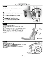
Page 11: ...vis Pin and Small Hair Pin STEP 1 Unfolding MoJack 750XT Pull locking pin out to unlock Raise the Tower by pulling up on the Grip Handle Once the Tower is in the vertical position lift up on the Grip Handle and drop the Tower into the Base The tower will be securely locked in place when the locking pin retracts and the tower is snug in the channel behind the crossbar Tower Locking Pin locked posit...

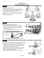
Page 12: ... Steps 12 16 on how to raise and lower the Lift Arm Practice Step 21 if you intend to raise or lower the mower with a drill attachment Operating Instructions Push Pin Lift Arm Insert Wheel Pad STEP 4 Installing Wheel Pads Slide Wheel Pads onto Lift Arm Inserts and temporarily secure with Push Pins STEP 3 Installing Lift Arm Inserts Slide Lift Arm Inserts into both sides of the Lift Arm and secure ...

Page 13: ...s for Proper Tire Size Adjust Support Rods on Wheel Pads to accommodate the front tire size of the mower Please refer to the chart below for proper Support Rod placement based on the diameter of the mower s front tires Secure Support Rods to Wheel Pads with Large Hair Pins Reverse Wheel Position Forward Wheel Position Support Rod Large Hair Pin See page 20 for more more detailed guide 10 11 5 25cm...

Page 14: ...ds Operating Instructions STEP 11 Adjusting the Crank Handle optional The optimal Crank Handle length is in the longer setting Some mowers have brush guards or larger hoods that interfere with the longer Crank Handle The Crank Handle can be adjusted by removing the Nylock Nut and Carriage Bolt and re attaching in the shorter setting 10 Wheel Pad Cross Bar Support Rod Safety Strap Nylock Nut Carria...

Page 15: ...e Safety Holes on the Tower when raising Note When lowering the Lift Arm the Carrier Locking Pin must be held out by the operator until it clears the bottom Safety Hole Safety Hole Carrier Locking Pin Pull Out to Unlock and Lower Wheel Chock STEP 12 Raising the Mower Raise the mower by rotating the Crank Handle clockwise See Step 22 for raising the mower with drill attachment Do not attempt to lif...
Page 16: ...Release the parking brake Mower must be in neutral Disengage transmission if neccessary Pull and hold the Carrier Locking Pin out and turn the Crank Handle counter clockwise until Wheel Pads are firmly on the ground The Carrier Locking Pin must be pulled out until it clears the bottom Safety Hole Do not force the handle past the lock point as this may damage the Screw Thread Safety Hole Carrier Lo...
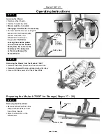
Page 17: ...hook the Lift Arm from the Carrier Store the Small Hair Pin and Clevis Pin in the Lift Arm STEP 18 Removing LIft Arm Inserts Remove Lift Arm Push Pins and pull Lift Arm Inserts from the Lift Arm Store the Push Pins in the Lift Arm Lift Arm Carrier STEP 20 Raise Carrier Raise the Carrier by turning the Crank Handle clockwise until the Carrier Locking Pin drops into the safety hole Safety Hole Carri...

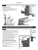
Page 18: ...lower the Lift Arm Carrier Locking Pin must be pulled out when lowering until it clears the bottom Safety Hole Follow all other operating instructions while using the drill attachment Replace the Crank Handle for future use Operator must have a firm grip on the drill before raising or lowering the Lift Arm 3 8 Square Driver Square Receiver Screw Thread STEP 21 THE MOJACK 750XT IS NOW READY FOR STO...
Page 19: ...ter every 50 uses or at least once a year Spray grease or lube in Locking Pin holes and shaft after every 50 uses or at least once a year Optional Check for Carrier Locking Pin operation Turn top Crank Handle to raise the Lift Arm to the first Safety Hole and listen for click as pin pops into hole After a click is heard reverse direction of Crank Handle rotation without pulling on the Carrier Lock...

Page 20: ...MoJack 750XT Lift 20 10 11 5 25cm 29cm Tire Size 12 15 30cm 38cm Tire Size 15 5 17 39cm 44cm Tire Size Support Rod Guide for Tire Sizes Not for use with tires over 17 44cm in size ...

Page 21: ...nadas en fábrica para garantizar el cumplimiento de las normas de seguridad pertinentes NOTA Guarde este manual para referencia futura Introducción Patente s U S 8 448 920 and 8 387 953 2014 MoJack Distributors LLC MoJack es una marca registrada de MoJack Distributors LLC MoJack 750XT es una marca registrada de MoJack Distributors LLC Submit your questions online at Envie sus preguntas por Interne...

Page 22: ...oras salvo que utilice el accesorio adecuado Apague siempre el motor y e750XTraiga la llave antes de comenzar a trabajar en la podadora Nunca haga funcionar el motor de la podadora mientras utiliza el elevador MoJack 750XT No exceda la capacidad de elevación límite de 750 libras 340 kg Si la torre del MoJack EX se inclina al elevar o bajar la podadora eso indica que existe una sobrecarga Retire la...

Page 23: ...ack que haya sido alterada o ajustada de alguna forma en relación con el modelo original No cubrirá ningún producto MoJack que resulte dañado debido a uso incorrecto o excesivo accidente o negligencia Esta garantía no cubre daños imprevistos o derivados Cuál es el período de cobertura Dos años para uso residencial y un año para uso comercial a partir de la fecha de compra por el propietario origin...

Page 24: ...arts List 6 Item No Qty Description Inserto del brazo elevador Asa de seguridad Manivela Varilla de soporte Correa de seguridad 2 1 1 2 2 7 8 9 10 1 Item No Qty Description Torre Brazo elevador Base Rueda Tope de rueda 1 1 1 2 2 2 3 4 5 6 5 4 6 Carrier ...

Page 25: ...uje Pasador de horquilla Horquilla chica Horquilla grande 1 2 3 3 3 4 1 1 2 19 12 13 14 15 16 17 18 Herramientas necesarias para el montaje Llave inglesa de 19 mm 2 Llave inglesa de 13 mm 1 14 Tuerca Nylock M12 1 75 15 Tuerca Nylock M8 1 25 18 Horquilla chica 19 Horquilla grande 11 Tornillo de cabeza M12 1 75 X 80 13 Perno de carruaje M8 1 25 X 20 12 Tornillo de cabeza M12 1 75 X 65 16 Pasador de ...

Page 26: ...tes y materiales Si faltan partes o materiales póngase en contacto con MoJack llamando al 1 877 575 3173 o por correo electrónico a parts themojack com PASO 2 Monte la rueda a la base insertando el tornillo de cabeza y la tuerca Nylock y fíjelos Repita el procedimiento con la segunda rueda Nota No apriete demasiado la tuerca Nylock 4 3 12 14 Sujete la torre a la base usando el tornillo de cabeza y...

Page 27: ...anivela El orificio más cercano al asa de goma proporcionará un radio de 6 15 cm para hacer funcionar la manivela El otro orificio proporcionará un radio de 8 20 cm facilitando la manipu lación de la manivela Utilice el orificio que funcione mejor con su modelo de podadora 1 8 13 15 PASO 6 Cuelgue el brazo elevador en el transportador enganchando el área ranurada del brazo elevador sobre la barra ...

Page 28: ...razo elevador y fíjelos con pasadores de empuje como se indica 6 2 16 Prepare los topes de rueda para instalar colocando las varillas de soporte y las horquillas 5 11 19 Coloque los topes de rueda a ambos lados de los insertos del brazo elevador y fíjelos con pasadores de empuje Nota los topes de rueda se pueden mover hacia adentro o hacia afuera para adaptarse a los distintos tamaños de podadora ...

Page 29: ...e utilizar el elevador MoJack 750XT lea con atención todo el manual Algunos pasos de las instrucciones de funcionamiento son iguales a las instrucciones de montaje Las instrucciones de funcionamiento mostrarán un ciclo de trabajo completo del elevador MoJack 750XT ...

Page 30: ...recta Fije el brazo elevador al transportador con pasadores de horquilla y horquilla Cómo desplegar el elevador MoJack 750XT Tire el pasador de bloqueo a desbloquear Levante la Torre tirando hacia arriba de la manija de agarre Una vez que la torre está en la posición vertical levante la manija de agarre y colocar la torre en la Base The tower will be securely locked in place when the locking pin r...

Page 31: ...ador de empuje Brazo elevador Instalación de los topes de rueda Deslice los topes de rueda en los insertos del brazo elevador y fíjelos provisoriamente con pasadores de empuje Pasador de empuje Inserto del brazo elevador Tope de rueda Familiarícese con el elevador MoJack 750XT Practique cómo subir y bajar el brazo elevador antes de intentar elevar la podadora ver pasos 12 a 16 cómo subir y bajar e...

Page 32: ...e soporte según el diámetro de los neumáticos delanteros de la podadora Fije las varillas de soporte a los topes de rueda con horquillas grandes Consulte la página 39 para obtener información más detallada 10 11 5 25 cm 29 cm 12 15 30 cm 38 cm 15 5 17 39 cm 44 cm GUÍA DE VARILLAS DE SOPORTE PARA TAMAÑOS DE NEUMÁTICO Varilla de soporte Horquilla grande Posición inversa de los neumáticos delanteros ...

Page 33: ...erte la ayuda Rod en el lazo en la correa de la seguridad separando la ayuda Rod y después deslizando el lazo de la correa de la seguridad a través y reatando la ayuda Rod Ajuste las correas de seguridad sobre la parte superior del neumático para fijar la podadora a los topes de rueda 10 Varilla de soporte Correa de seguridad Barra transversal del tope de rueda Ajuste de la manivela opcional La lo...

Page 34: ... de bloqueo Levante el brazo elevador hasta que el pasador de bloqueo del transportador quede colocado en el orificio de seguridad El pasador de bloqueo del transportador se introduce automáticamente en los orificios de seguridad cuando el transportador pasa por los orificios ubicados en la torre al elevarse Nota Al bajar el brazo elevador el operador debe tirar del pasador de bloqueo del transpor...

Page 35: ...ificio de seguridad inferior No fuerce la manivela más allá del punto de bloqueo de lo contrario puede dañar la rosca del tornillo Orificios de seguridad Retiro de la podadora del elevador MoJack 750XT Quite las correas de seguridad de los neumáticos delanteros de la podadora La e750XTracción de las varillas de soporte es opcional en este paso Conduzca o haga rodar la podadora para alejarla de los...

Page 36: ... de empuje Pasador de empuje Brazo elevador Desenganche del brazo elevador E750XTraiga la horquilla pequeña y el pasador de horquilla del brazo elevador Desenganche el brazo elevador del transportador levantando y tirando de la parte delantera del brazo elevador Guarde la horquilla y el pasador de horquilla en el brazo elevador PASO 20 Levante el transportador Levante el soporte girando el transpo...

Page 37: ...r subir el brazo elevador y en sentido inverso antihorario para hacer descender el brazo elevador Se debe tirar del pasador de bloqueo del transportador durante el descenso hasta liberar el orificio de seguridad inferior Siga todas las demás instrucciones de funcionamiento para utilizar el accesorio de taladro Vuelva a colocar la manivela para el uso posterior El operador debe sostener el taladro ...

Page 38: ...rificio de cada 50 usos o por lo menos una vez al año Opcional Controle del funcionamiento del pasador de bloqueo del transportador Haga girar la manivela para hacer subir el brazo elevador al primer orificio de seguridad y escuche si se produce un clic cuando el pasador se inserta en el orificio Después de escuchar el clic invierta la dirección de la rotación de la manivela sin e750XTraer el anil...

Page 39: ...maño de neumático 10 11 5 25 cm 29 cm Tamaño de neumático 12 15 30 cm 38 cm Tamaño de neumático 15 5 17 39 cm 44 cm Guía de varillas de soporte para tamaños de neumáticos No es para uso con neumáticos de más de 17 44cm de tamaño ...

Page 40: ...2014 MoJack Distributors LLC MoJack and the MoJack logo are registered trademarks of MoJack Distributors LLC MoJack 750XT is a trademark of MoJack Distributors LLC All rights reserved www theMoJack com 1 877 575 3173 ...

Reviews: