Section 9 - Wiring Details
WARNING
Ensure that you have fully read “Section 3 - Safety” before connecting the
E-Drive controller.
9.1 Three Phase Supply Cable and Miniature
Circuit Breaker
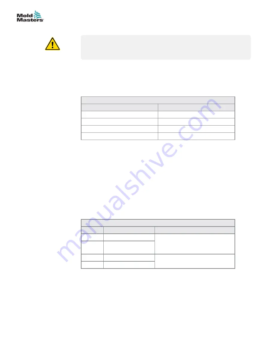
Please take extreme care when connecting the controller to the three-phase
supply. Incorrect connection may result in damage to the controller.
Cable Marking
Supply Description
L1
Phase 1
L2
Phase 2
L3
Phase 3
Earth Symbol
Eartth
*N.B. Cable colors may vary therefore wire up according to the cable
markings.
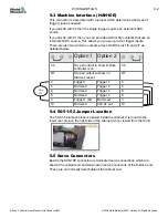
A suitably rated three-phase miniature circuit breaker (MCB) is located on
the rear of the cabinet just above the supply cable inlet. This is the safety
overload trip for the cabinet as well as the main user-switch for isolation. It
can be locked off by using a proprietary shield locking device.
9.2 Auxilliary Input
A HAN4A cabinet connector provides a simple IO function.
The input (Pins 1 &2) looks for a closing signal from the associated hot
runner controller. This indicates that the mold is up to temperature and must
be present before the E-Drive can be used.
Pin
Connection
Input / Output
1
Auxiliary Input signal Input from associated hot runner
controller
2
Auxiliary Input
Ground
3
Not Used
spare function
4
Not Used
9-1
WIRING DETAILS
E-Drive Controller User Manual (with Pendant HMI)
© 2020 Mold-Masters (2007) Limited. All Rights Reserved.
Summary of Contents for E-Drive Series
Page 1: ...version 3 User Manual with Pendant HMI Original Instructions ...
Page 2: ......
Page 26: ......
Page 36: ......


