User
Guide
for
Axoclamp
900A
Associated
with
the
current
flow
(I)
in
a
microelectrode
is
a
voltage
drop
across
the
microelectrode
that
depends
on
the
product
of
the
current
and
the
microelectrode
resistance
(R
e
).
This
unwanted
IR
voltage
drop
adds
to
the
recorded
potential.
The
Bridge
Balance
control
can
be
used
to
balance
out
this
voltage
drop
so
that
only
membrane
potential
is
recorded.
The
term
“Bridge”
refers
to
the
original
Wheatstone
Bridge
circuit
used
to
balance
the
IR
voltage
drop
and
is
retained
by
convention.
The
particular
setting
required
to
balance
the
Bridge
is
a
measure
of
the
microelectrode
resistance,
and
the
microelectrode
resistance
can
be
read
from
the
Axoclamp
900A
Commander.
Discontinuous
Current
Clamp
(DCC)
Mode
In
Discontinuous
Current
Clamp
(DCC)
mode,
CHANNEL
1
is
cyclically
used
to
pass
current.
The
voltage
recorded
at
the
tip
of
CHANNEL
1
is
memorized
by
a
sample
‐
and
‐
hold
circuit
in
between
each
current
‐
passing
period
after
all
transient
voltages
due
to
current
passing
have
decayed.
Thus
the
membrane
potential
can
be
recorded
independently
of
the
IR
voltage
drop
across
the
microelectrode.
The
advantage
of
DCC
mode
compared
with
I
‐
Clamp
mode
is
that
it
is
tolerant
of
small
changes
in
microelectrode
resistance.
The
disadvantage
is
that
DCC
mode
is
noisier
than
I
‐
Clamp
mode.
During
DCC
mode
CHANNEL
2
is
still
in
I
‐
Clamp
mode
and
can
be
used
for
continuous
current
passing.
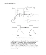
The
principles
of
operation
are
outlined
in
the
block
diagram
and
timing
diagram
of
Figure
46.
The
voltage
recorded
by
the
microelectrode
(V
1
)
is
buffered
by
a
unity
‐
gain
head
stage
(A1).
Assume
that
V
1
is
exactly
equal
to
the
instantaneous
membrane
potential
(V
m
).
Switch
S2
briefly
closes
thereby
enabling
the
voltage
on
the
holding
capacitor
(C
H
)
to
charge
up
to
the
value
of
V
m
.
S2
opens
again
after
the
“sample”
period
and
V
m
is
held
by
C
H
.
A
buffer
amplifier
(A2)
interfaces
C
H
to
the
recording
apparatus.
This
switch,
88


