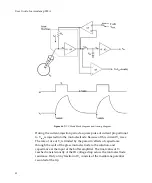
Guide
to
Electrophysiological
Recording
current
is
measured
from
the
voltage
drop
across
this
resistor.
If
your
current
‐
passing
microelectrode
resistance
is
5
M
Ω
and
the
output
voltage
180
V,
then
~120
V
drops
across
the
current
sensing
resistor
and
only
~60
V
across
the
microelectrode.
The
effective
gain
of
the
clamp
is
reduced
by
one
third
and
thus
the
frequency
response
is
compromised
(see
Tuning
the
Voltage
‐
Clamp—Fidelity
and
Stability
section).
Generally
this
is
not
a
significant
problem
since
the
high
output
compliance
of
the
TEVC
simply
allows
a
higher
clamp
gain
to
be
used.
If
you
are
using
series
current
measurement
and
have
headstages
with
different
H
values,
use
the
headstage
with
the
higher
H
value
(which
has
the
lower
value
for
the
current
sensing
resistor)
for
the
current
‐
passing
microelectrode.
Tuning
the
Voltage
‐
Clamp—Fidelity
and
Stability
The
object
of
tuning
the
voltage
clamp
is
to
maximize
the
feedback
gain.
There
are
two
reasons,
first
the
bandwidth
of
the
clamp
is
strongly
dependent
on
the
gain
and
second,
the
fidelity,
or
accuracy,
with
which
the
voltage
clamp
tracks
the
command
potential
is
dependent
on
the
gain.
Fidelity
The
steady
‐
state
membrane
potential
(V
m
)
after
a
step
change
in
the
command
voltage
(V
cmd
)
is:
1
+
=
K
μ
K
μ
V
V
cmd
m
where
μ
is
the
gain
of
the
clamp
amplifier
and
K
is
the
attenuation
of
the
clamp
amplifier
caused
by
the
cell
membrane
resistance
(R
m
)
and
the
resistance
(R
e2
)
of
the
output
microelectrode
(CHANNEL
2).
2
+
=
e
m
m
R
R
R
K
As
the
product
μ
K
becomes
very
large,
the
difference
between
V
m
and
V
cmd
becomes
very
small.
Ideally,
the
error
is
very
low,
just
a
fraction
of
one
percent.
μ
is
set
by
the
Gain
glider
in
the
V
‐
Clamp
Control
section
of
the
TEVC
tab
of
the
Axoclamp
900A
Commander.
In
TEVC
mode
the
gain
can
103


