Setup
and
Tutorials
cyclically
used
to
pass
current.
The
voltage
recorded
at
the
tip
of
CHANNEL
1
is
measured
by
a
sample
‐
and
‐
hold
circuit
in
between
each
current
‐
passing
period
and
after
all
transient
voltages
due
to
current
passing
have
decayed.
Thus
the
membrane
potential
can
be
recorded
independently
of
the
IR
voltage
drop
across
the
microelectrode.
The
advantage
of
DCC
mode
compared
with
I
‐
Clamp
mode
with
Bridge
Balance
is
that
it
is
tolerant
of
small
changes
in
microelectrode
resistance.
The
disadvantage
is
that
DCC
mode
is
noisier
than
I
‐
Clamp
mode.
During
DCC
mode
CHANNEL
2
can
be
used
in
I
‐
Clamp
mode
for
continuous
current
passing.
Equipment
required:
CLAMP
‐
1U
model
cell.
HS
‐
9A
×0.1.
HS
‐
9A
×1.
Follow
the
steps
of
Tutorial
1
before
beginning
these
instructions.
1.
In
Channel
1
select
DCC
mode.
2.
Set
DCC
Rate
to
10
kHz.
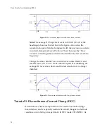
Note:
When
DCC
mode
is
selected
the
Scope
window
display,
with
the
“monitor”
waveform,
should
automatically
appear
on
the
computer
screen.
35


