User
Guide
for
Axoclamp
900A
3.
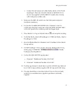
Connect
the
CLAMP
‐
1U
model
cell
to
the
HS
‐
9A
×1
headstage,
and
the
ground
wire
between
the
CLAMP
‐
1U
and
the
HS
‐
9A
×1.
4.
Press
the
Reset
to
Program
Defaults
button
and
accept
the
warning.
5.
In
the
Headstage
2
tab
select
HVIC.
6.
In
I
‐
CLAMP
2
tab,
set
1000
nA
of
Tune
current
and
enable
the
Tuning
checkbox.
7.
Connect
scope
channel
1
to
SCALED
OUTPUT
1.
8.
The
Channel
1
SCALED
OUTPUT
Signal
selected
should
be
“Headstage
2,
0.1×
Membrane
Potential”.
9.
Connect
scope
channel
2
to
SCALED
OUTPUT
2.
10.
The
Channel
2
SCALED
OUTPUT
Signal
selected
should
be
“Headstage
2,
0.1×
Membrane
Current”.
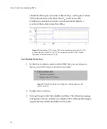
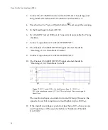
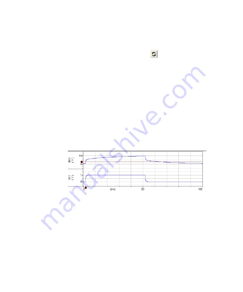
Figure
37.
HVIC
mode.
IN0
is
the
headstage
voltage
×0.1
(100
V
p-p
).
IN1
is
the
membrane
current
(1
V/
μ
A).
The
rise
time
of
the
current
signal
is
about
1
ms.
The
waveform
shapes
are
similar
to
normal
I
‐
Clamp.
However,
the
speed
is
slower
but
compliance
is
much
higher
(up
to
±180
V
p-p
).
11.
If
the
membrane
voltage
waveform
is
less
than
±10
V
p-p
then
you
can
use
Bridge
Balance
if
the
signal
selection
is
“Membrane
Potential
(1
mV/mV)”.
56


