Digidata 1550 Low-Noise Data Acquisition System User Guide
12
5023399 A
Digital Outputs
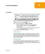
Digital Outputs 0–7 are on the front panel of the Digidata 1550 digitizer.
These output levels can be set to high (+5 V) or low (0 V) TTL-level states.
They can be used to trigger a wide variety of external devices.
Start and Tag Input Triggers
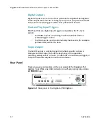
START and TAG are digital input triggers compatible with TTL-level
signals.
•
The START input is used to begin data acquisition from an
external trigger source.
•
The TAG input is used to automatically mark events (for example,
perfusion ON) within the data.
Scope Output
The SCOPE output is a digital signal that reflects specific actions in
Clampex and AxoScope, such as the beginning of an acquisition
recording, sweep, event, or level. It is useful as an oscilloscope trigger, or
to synchronize data acquisition with other devices.
Rear Panel
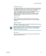
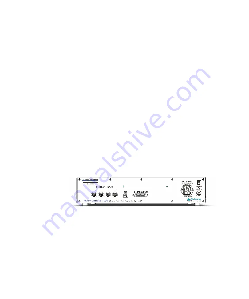
There are several connectors on the rear panel of the Digidata 1550
digitizer: four BNCs, one USB connector, one 25-pin connector, and one
AC POWER
input.
Figure 3-2:
Rear panel of the Digidata 1550 digitizer.


