background image

5031496 G
August 2022

QPix 420

Colony Picking System

User Guide

Summary of Contents for QPix 420

Page 1: ...5031496 G August 2022 QPix 420 Colony Picking System User Guide...

Page 2: ...r license to use or permit others to use such manufacturers and or their product names as trademarks Each product is shipped with documentation stating specifications and other technical information M...

Page 3: ...the QPix 420 System 13 Chapter 2 QPix 420 System Instrument Overview 15 Front Panel Controls and Display 16 Instrument Connections 17 Compressed Air Supply 18 Using Barcodes 18 Computer System Requir...

Page 4: ...Blue White Regional Picking Processes 120 Running Blue White Regional Picking Processes 128 Chapter 11 Control Plate Creation Processes 139 Creating and Editing Control Plate Creation Processes 140 R...

Page 5: ...205 Moving the Instrument 206 Adding a New User to the SQL Server Database 207 Running the Software as an Administrator 207 Resetting the Path to the SQL Server 207 Obtaining Support 209 Chapter 18 Tr...

Page 6: ...QPix 420 Colony Picking System User Guide 6 5031496 G...

Page 7: ...of other types of hazards such as biohazard electrical or laser safety warnings as are described in the text of the warning When warnings and cautions are displayed in this guide be careful to follow...

Page 8: ...All safety instructions must be read and understood before proceeding with the installation maintenance and servicing of all modules Power off the instrument and disconnect the power cord before you...

Page 9: ...als being used Electrical Safety To prevent electrically related injuries and property damage inspect all electrical equipment before use and immediately report all electrical deficiencies Contact Mol...

Page 10: ...V light to prevent the risk of damage from UV radiation Magnet Safety Persons with external or implanted medical devices need to evaluate the risks related to these devices before entering an area whe...

Page 11: ...ea must be clearly marked with an applicable biohazard sign WARNING Never use the instrument in an environment where potentially damaging liquids or gases are present Moving Parts Safety To prevent in...

Page 12: ...page 11 for details Avoid spilling liquids on the system Fluid spilled into internal components creates a potential shock hazard Wipe up all spills immediately Do not operate the system if internal c...

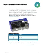
Page 13: ...as protein engineering protein evolution directed or enzyme evolution protein expression transformation and sub clone management The QPix 420 system is available with white light or fluorescent imagin...

Page 14: ...uses an LED based light source and preset filter pairs for selecting fluorescence excitation and emission wavelengths and a sensitive monochrome CCD camera for image acquisition The fluorescence head...

Page 15: ...you run a process The door prevents UV light from passing through during operation The bed of the instrument contains source and destination receptacle positions The bed also contains wash baths whic...

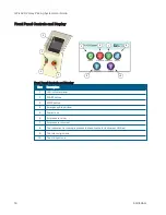
Page 16: ...em Description 1 LCD indicator panel 2 START button 3 STOP button 4 Emergency Stop button 5 Power is on 6 Air pressure is low 7 Air pressure is correct 8 The instrument is running a process not applic...

Page 17: ...ht side of the instrument 1 2 3 4 5 6 Item Description 1 Power Inlet Instrument Mains 2 Power Outlets Computer and Monitor 3 Ethernet port 4 Compressed air inlet 5 Fuse carrier Instrument Mains 6 Fuse...

Page 18: ...h the filter regulator inlet Use only 6 mm OD polyurethane pneumatic hose rated for more than 100 psi to connect to the air inlet CAUTION The filter regulator is factory set to 0 69 MPa 100 psi at 60...

Page 19: ...10 64 bit Windows 7 32 bit Memory 4 GB RAM Data Connection 10 100 Ethernet port Camera Connection USB 2 0 port Minimum Computer System Requirements CAUTION Do not replace the computer operating the sy...

Page 20: ...QPix 420 Colony Picking System User Guide 20 5031496 G...

Page 21: ...e window below the menus New Process gives you a full set of options for creating and managing processes and system maintenance See New Process Options on page 23 Templates displays a list of saved te...

Page 22: ...Recent Processes displays a list of recently opened processes Switch User can be used in a multiple user environment to log off the current user so that a different user can log on Exit closes the Na...

Page 23: ...m receptacles using the regional process See Blue White Regional Picking Processes on page 119 Control Plate Creation creates a batch of plates containing control samples These can be created by picki...

Page 24: ...s process whenever the head is returned to the actuator or whenever the actuator is hit as this can have a negative effect on picking precision See Aligning the Camera on page 202 Instrument Utilities...

Page 25: ...is from 0 69 MPa to 0 83 MPa 100 psi to 120 psi If you are using a standalone air compressor confirm that the power cord for the compressor is properly connected and that power to the power outlet is...

Page 26: ...the computer to turn off 3 Push the Stop button on the front panel to switch off the instrument 4 Turn off the power at the mains or disconnect the power cord to the instrument 5 Turn off the air sou...

Page 27: ...2 7 Prepare plates QTrays OmniTrays or Petri dishes based on the requirements for your application 8 Select and run the desired process For information about selecting defining and running processes s...

Page 28: ...es use the software Change Head process to safely move the actuator To change the head 1 From the Navigation window under Utility Processes double click the Instrument Utilities icon 2 In the Instrume...

Page 29: ...or whenever it needs cleaning wipe the exterior of the head with a cloth using 70 ethanol To store the head slide it into its metal cover with the pins facing inward and then secure it in place with t...

Page 30: ...QPix 420 Colony Picking System User Guide 30 5031496 G...

Page 31: ...lly clean the instrument interior To run a Sanitise process 1 From the Navigation window under Utility Processes double click Instrument Utilities 2 In the Instrument Utilities window double click San...

Page 32: ...ow select a Sanitise Profile type the duration in seconds for the UV light to remain on The default duration is 600 seconds 10 minutes 4 Confirm that the bed is clear and that the door is closed Tip T...

Page 33: ...ycles can contain one or more wash bath steps that can be created in the Manage Sanitise Profiles window Tip You cannot edit Sanitise profiles when setting up a routine for a process While you are wor...

Page 34: ...file dialog in the Name field enter a short descriptive name for the profile 4 Select one of the following options for the wash profile Select Single Stage to use the same wash cycle before and during...

Page 35: ...tility Processes double click Manage Sanitise Profiles 2 In the Manage Sanitise Profiles window in the Profiles table click the profile you want to edit If the profile is a Single Stage profile the St...

Page 36: ...conds list enter the number of seconds to dry the pins with the halogen dryer 7 From the Wait After Drying seconds list enter the number of seconds to wait before moving on to the next step or ending...

Page 37: ...1 From the Navigation window under Utility Processes double click the Manage Sanitise Profiles icon 2 In the Manage Sanitise Profiles window in the Profiles table click the profile you want to delete...

Page 38: ...QPix 420 Colony Picking System User Guide 38 5031496 G...

Page 39: ...containing control samples These can be created by picking colonies from source receptacles into destination wells See Control Plate Creation Processes on page 139 Create New Regional Tray adds new pl...

Page 40: ...ow under Picking Processes double click Picking 2 In the Picking window click Picking Type to view the picking type options Select White Light to use only white light to illuminate and identify the co...

Page 41: ...he routine is of the same type as the one you are creating then the imported routine displays in the Select Routine list Exporting Routines To export a routine click Export and then navigate to the lo...

Page 42: ...ow the system to automatically assign a valid random barcode and continue the routine 3 Use the Validation Barcode list to define the barcodes for source receptacles If the scanned barcode on a source...

Page 43: ...om which to import the identifiers To remove an identifier from the list click the identifier in the list and then click Remove To generate a defined list of identifiers for the source receptacles cli...

Page 44: ...py check box and from the Select Copy Microplate list select the plate type to use for a duplicate copy of the destination plate This sends the picking head to inoculate a second plate without returni...

Page 45: ...sferring the picked colonies to the destination plate For the fastest transfer rate select All to use all available picking pins to pick colonies before inoculating the destination plate For smaller p...

Page 46: ...vailable 5 In the Picking Depth Into Agar mm field enter a value in millimeters to define the depth that the pins are to be inserted in the agar for picking 6 Select the Limit Max Number of Features P...

Page 47: ...r the front of the instrument 3 Open the front door 4 Install the picking head To remove an installed head unscrew and remove the thumbscrew and washer on the left that secures the head to the actuato...

Page 48: ...nes on page 40 If you do not need to make changes to the routine select the Skip Steps check box before clicking Next 3 Review the configured settings for the routine See Viewing the Settings Summary...

Page 49: ...nies are detected adjust the test image in this window using the Exposure and Gain settings the Detection settings the Display settings the Debris settings and the Depth settings Each detected feature...

Page 50: ...ain settings click Grab Image to apply the new settings to the test image 3 Select the Detection tab 4 Select the Use Auto Thresholding check box to have the software automatically detect the colonies...

Page 51: ...shold Each Frame check box again and enter the value from the Threshold field into the High Limit field 7 Select the Invert Image check box to make dark areas bright and bright areas dark Tip This is...

Page 52: ...ight for a long pin head to descend into the source agar Note Further refinement for colony detection can be done on a higher resolution image in the Feature Selection window 15 Click Next to go to th...

Page 53: ...o expose the sample to light when acquiring the image Adjust the Gain to increase the image signal without changing the light exposure After you adjust the Exposure or Gain settings click Grab Image t...

Page 54: ...t without a yellow ring in the test image is excluded from becoming a pickable object Drag the Zoom slider below the image to get a closer look at the image and drag the Contrast slider to change the...

Page 55: ...ou want to change When clicked as an override the yellow marked pickable objects change to blue and become unpickable To undo the selection right click over the image map and select Pick Item The obje...

Page 56: ...erimeter divided by the area of the colony so that irregular shaped colonies are closer to 0 and colonies that are more of a perfect circle are closer to 1 A colony equal to or less than 0 65 is not p...

Page 57: ...e intensity threshold For Between enter two values to define the range 4 Change the pickable property of individual objects To define an object as pickable right click the object and select Pick Item...

Page 58: ...ocess If you create a new routine the Continue or Save New Routine dialog displays To save the settings for the routine before you continue click Save Routine enter a Name and a short Description for...

Page 59: ...ct Make Copy for the routine Destination Barcode is the barcode of the destination receptacle that is currently being inoculated Destination Offset is the reference well for where the pins are lowered...

Page 60: ...nstrument deck 5 Close the instrument door 6 Click Next to continue running the picking routine If you click Continue With Image Review the system takes a white light test image of the source receptac...

Page 61: ...r the front of the instrument 3 Open the front door 4 Install the picking head To remove an installed head unscrew and remove the thumbscrew and washer on the left that secures the head to the actuato...

Page 62: ...QPix 420 Colony Picking System User Guide 62 5031496 G...

Page 63: ...Note Before running a picking process it is important that you do the cleaning and set up procedures in Preparing to Run Processes on page 27 If this is your first picking process you must edit or cr...

Page 64: ...page 70 Changing the Picking Head on page 70 Note Some steps that are included in these procedures might not be available depending on the features included with the instrument and license Opening the...

Page 65: ...Routines Before you can import a routine you must export the routine from the other computer in xml format and then save the export file on the system computer To import the xml file click Import and...

Page 66: ...ode Note If the system fails to identify a barcode for the source receptacle the routine ends since the source requires a valid barcode Click Auto Generate to allow the system to automatically assign...

Page 67: ...To import identifiers for the source receptacles from a text or csv file click Import and then select the file from which to import the identifiers To remove an identifier from the list click the iden...

Page 68: ...Click Fill All Microplates to fill every selected well of a destination plate before starting a new destination plate Click New Microplate for Each Position to start a new destination plate whenever...

Page 69: ...rofiles are not suitable for the picking routine exit the picking process and create a new Sanitise profile See Creating and Editing Sanitise Profiles on page 33 5 Click Next to define options for the...

Page 70: ...ick Move to Load Position to move the picking head arm to the loading position 2 When the message displays make sure that the bed is clear of obstructions and that the door is closed and then click OK...

Page 71: ...the picking routine to run See Selecting Blue White Picking Routines on page 64 If you do not need to make changes to the routine select the Skip Steps check box before clicking Next 3 Review the sett...

Page 72: ...destination plates To make sure that only blue or white colonies are detected adjust the test image in this window using the Exposure and Gain settings the Detection settings the Display settings and...

Page 73: ...conds from 1 to 2000 to expose the sample to light when acquiring the image Adjust the Gain to increase the image signal without changing the light exposure Tip Molecular Devices recommends not changi...

Page 74: ...Range that starts near the left side of the histogram and ends to the left of the large spike that represents the largest area which is the agar To manually select White Colonies increase the minimum...

Page 75: ...or colony detection can be done on a higher resolution image in the Feature Selection window 10 Click Next to go to the next step Selecting Blue White Colonies for Picking After you adjust and refine...

Page 76: ...he objects and the background To save the image in bmp jpg or png format click Export Image To select a smaller region of interest ROI in the image draw a polygon around the region To draw a polygon c...

Page 77: ...change When clicked as an override the yellow marked pickable objects change to blue and become unpickable To undo your individual selection right click over the image map and select Pick Item The ob...

Page 78: ...perimeter divided by the area of the colony so that irregular shaped colonies are closer to 0 and colonies that are more of a perfect circle are closer to 1 A colony equal to or less than 0 65 is not...

Page 79: ...escence intensity threshold For Between enter two values to define the range 4 Change the pickable property of individual objects To define an object as pickable right click the object and select Pick...

Page 80: ...ocess If you create a new routine the Continue or Save New Routine dialog displays To save the settings for the routine before you continue click Save Routine enter a Name and a short Description for...

Page 81: ...you select Make Copy for the routine Destination Barcode is the barcode of the destination receptacle that is currently being inoculated Destination Offset is the reference well for where the pins are...

Page 82: ...ose the instrument door 6 Click Next to continue running the picking routine If you click Continue With Image Review the system takes a white light test image of the source receptacles and the Test Im...

Page 83: ...These can be created by picking colonies from source receptacles into destination wells See Control Plate Creation Processes on page 139 Create New Regional Tray adds new plate source definitions to...

Page 84: ...ncluded in these procedures might not be available depending on the features included with the instrument and license Opening the Zone of Inhibition Detection Picking Window To open the Zone of Inhibi...

Page 85: ...atabase Importing Routines Before you can import a routine you must export the routine from the other computer in xml format and then save the export file on the system computer To import the xml file...

Page 86: ...fails to identify a barcode for the source receptacle the routine ends since the source requires a valid barcode Click Auto Generate to allow the system to automatically assign a valid random barcode...

Page 87: ...k Insert To import identifiers for the source receptacles from a text or csv file click Import and then select the file from which to import the identifiers To remove an identifier from the list click...

Page 88: ...es By Columns or By Rows 5 Define the Deposit Strategy using one of the following options To fill every selected well of a destination plate before starting a new destination plate click Fill All Micr...

Page 89: ...are not suitable for the picking routine exit the picking process and create a new Sanitise profile See Creating and Editing Sanitise Profiles on page 33 5 To define the source receptacle options cli...

Page 90: ...ick Move to Load Position to move the picking head arm to the loading position 2 When the message displays make sure that the bed is clear of obstructions and that the door is closed and then click OK...

Page 91: ...ing Window on page 84 2 Select the picking routine to run See Selecting Zone of Inhibition Detection Picking Routines on page 84 If you do not need to make changes to the routine select the Skip Steps...

Page 92: ...te Light Test Image In the Test Image window adjust the exposure level to best view the foreground image from the background using the Exposure and Gain settings To view the pixel intensity values in...

Page 93: ...ncrease the image signal without changing the light exposure Tip Increase the Exposure until the secondary layer is highly exposed and appears very white After you adjust the Exposure or Gain settings...

Page 94: ...lony to display the properties of that colony If a colony has not been selected as pickable the reason for the exclusion shows in red text Drag the Zoom slider below the image to get a closer look at...

Page 95: ...he gallery images to show the colonies that meet or fail to meet the criteria To exit the gallery click Return to Image Switch between the two views to define the pickable colonies To change the selec...

Page 96: ...colony is The value is a ratio of the longest diameter divided by the shortest diameter so oval shaped colonies are closer to 0 and round are closer to 1 The system default value is that a colony equ...

Page 97: ...colonies some shading for clearer visualization Select the Display Proximity Indicators check box to display connecting red lines between a detected colony and its closest neighbor Select the Shade Ex...

Page 98: ...ly doing such as Pick when the system is picking To turn the light table on or off click Light Table On or Light Table Off To safely pause the routine click Pause After all the colonies are picked fro...

Page 99: ...These can be created by picking colonies from source receptacles into destination wells See Control Plate Creation Processes on page 139 Create New Regional Tray adds new plate source definitions to t...

Page 100: ...cesses double click the Regional Picking icon 2 In the Regional Picking window click Picking Type to view the picking type options Select White Light to use only white light to illuminate and identify...

Page 101: ...utines Before you can import a routine you must export the routine from the other computer in xml format and then save the export file on the system computer To import the xml file click Import and th...

Page 102: ...when a barcode cannot be read Click Manual Prompt to open a dialog where you can enter a barcode or name for the receptacle Click Skip Receptacle to ignore the receptacle and scan the next receptacle...

Page 103: ...o import identifiers for the source receptacles from a text or csv file click Import and then select the file from which to import the identifiers To remove an identifier from the list click the ident...

Page 104: ...ur system you might have only one option in the Holder list in which case the Receptacle option is preset and cannot be changed If the type of source receptacle that you need is not listed contact Mol...

Page 105: ...e With the Reserve Wells for Region check box selected select the Skip Region If Picking Count is Zero check box to skip regions that have a picking count of zero 2 Select the Deposit Order to deposit...

Page 106: ...the Wash Between Partial Inoculation check box Clear this check box to wait until all pins are used for picking and inoculation before running the wash routine 3 In the Destination field enter the di...

Page 107: ...move the actuator into position near the front of the instrument 3 Open the front door 4 Install the picking head To remove an installed head unscrew and remove the thumbscrew and washer on the left...

Page 108: ...s on page 100 If you do not need to make changes to the routine select the Skip Steps check box before clicking Next 3 Review the configured settings for the routine See Viewing the Settings Summary o...

Page 109: ...the region to view in the receptacle image below the list The region is in red 2 Under Acquisition adjust the Exposure and Gain settings In the Exposure ms field enter the number of milliseconds from...

Page 110: ...make dark areas bright and bright areas dark 8 Select the Subtract Background check box to have the background become nearly black 9 Select the Display tab 10 Select the method for viewing the detecte...

Page 111: ...tion image and then displays the Feature Selection window If you are running a routine for white light and fluorescent imaging the Fluorescent Test Image window displays Adjusting the Fluorescent Test...

Page 112: ...tings 3 Click Next to capture and process a higher resolution image and then open the Feature Selection window Selecting Colonies for Regional Picking After you adjust and refine test images the syste...

Page 113: ...the image and drag the Contrast slider to change the contrast between the objects and the background To save the image in bmp jpg or png format click Export Image To change the selection of the syste...

Page 114: ...tions click the Remove User Selections icon to display the Remove User Selections dialog Click Yes If you run a routine for white light and fluorescent imaging two tabs are available The White Light t...

Page 115: ...qual to or greater than the value in this field is not picked Min Proximity mm sets the distance between colonies to be picked so that when picking one colony a different adjacent colony is not picked...

Page 116: ...gion on the receptacle image If you do not place a limit on the number of colonies to pick for each region all the numbers display in green If you create a limit on detectable colonies the number disp...

Page 117: ...ptacles and delivered to the destination plates the Finished Picking Current Batch dialog displays If there are no more source receptacles to be picked click Finish Picking and then click OK To contin...

Page 118: ...vities related to the source and destination receptacles click Details To save the detailed information in csv format click Export To close the picking details and return to the Regional Picking Summa...

Page 119: ...Note Before running a picking process it is important that you do the cleaning and set up procedures in Preparing to Run Processes on page 27 If this is the first picking process you must edit or cre...

Page 120: ...on page 122 Setting Destination Plate Options on page 124 Selecting the Regional Picking Source on page 124 on page 124 on page 125 Viewing the Settings Summary on page 126 After creating the routine...

Page 121: ...h the type of routine that you are creating are included in the list For example a white light and fluorescent imaging routine is not included in the Select Routine list if you are creating a White Li...

Page 122: ...re you can enter a barcode or name for the receptacle Click Skip Receptacle to ignore the receptacle and scan the next receptacle for a barcode Note If the system fails to identify a barcode for the s...

Page 123: ...sert To import identifiers for the source receptacles from a text or csv file click Import and then select the file from which to import the identifiers To remove an identifier from the list click the...

Page 124: ...he system you might have only one option in the Holder list in which case the Receptacle option is preset and cannot be changed If the type of source receptacle that you need is not listed contact Mol...

Page 125: ...destination plate With the Reserve Wells for Region check box selected select the Skip Region If Picking Count is Zero check box to skip regions that have a picking count of zero 2 Select the Deposit...

Page 126: ...Between Partial Inoculation check box Clear this check box to wait until all pins are used for picking and inoculation before running the wash routine 3 In the Destination field enter a value for the...

Page 127: ...OK to move the actuator into position near the front of the instrument 3 Open the front door 4 Install the picking head To remove an installed head unscrew and remove the thumbscrew and washer on the...

Page 128: ...White Regional Picking Routines on page 121 If you do not need to make changes to the routine select the Skip Steps check box before you click Next 3 Review the configured settings for the routine Se...

Page 129: ...es Adjusting the Blue White Regional White Light Test Image In the Test Image window all detected features are viewed as potential colonies to pick for inoculation of the destination plates To make su...

Page 130: ...apply the settings to the test image 3 Select the Detection tab 4 In the Threshold intensity histogram click and drag the red slider line to the right of the large spike to view the White colonies as...

Page 131: ...mage Click Image Only to display the detected colonies in white with yellow rings and a gray background Click Image and Overlay to display the detected colonies in green with yellow rings and a gray b...

Page 132: ...been selected as pickable the reason for the exclusion shows in red text Note During image processing each object with no yellow ring in the test image is excluded from becoming a pickable object Dra...

Page 133: ...map that you want to change When clicked as an override the yellow marked pickable objects change to blue and become unpickable To undo the selection right click over the image map and select Pick It...

Page 134: ...5 and is not picked Axis Ratio measures how oval the colony is The value is a ratio of the longest diameter divided by the shortest diameter so oval shaped colonies are closer to 0 and round colonies...

Page 135: ...some shading for clearer visualization Select the Display Proximity Indicators check box to display connecting red lines between a detected colony and its closest neighbor Select the Shade Exclusion...

Page 136: ...Finished Picking Current Batch dialog displays Continuing or Ending the Regional Picking Routine After all the colonies are picked from the source receptacles and delivered to the destination plates...

Page 137: ...tination plates used and missing source receptacles To save this information in csv format click Export To view details of all activities related to the source and destination receptacles click Detail...

Page 138: ...QPix 420 Colony Picking System User Guide 138 5031496 G...

Page 139: ...nal process See Blue White Regional Picking Processes on page 119 Control Plate Creation creates a batch of plates containing control samples These can be created by picking colonies from source recep...

Page 140: ...are included in these procedures might not be available depending on the features included with the instrument and license Opening the Control Plate Creation Window To open the Control Plate Creation...

Page 141: ...ting Routines Before you can import a routine you must export the routine from the other computer in xml format and then save the export file on the system computer To import the xml file click Import...

Page 142: ...r Devices to add a new plate type to the list See Obtaining Support on page 209 2 Select either to dip the pins a number of times or to stir the wells of the destination plate during inoculation To di...

Page 143: ...ick Next to define options for the source receptacle Setting Source Receptacle Options To set source and receptacle options 1 In the Source window from the Holder list select the type of holder used t...

Page 144: ...wells To deselect a well click the well again Wells that have not been selected show in light blue 3 Continue clicking receptacles and wells until all the control wells have been defined 4 Click Next...

Page 145: ...K to move the actuator into position near the front of the instrument 3 Open the front door 4 Install the picking head To remove an installed head unscrew and remove the thumbscrew and washer on the l...

Page 146: ...ecting Control Plate Creation Routines on page 140 If you do not need to change the routine select the Skip Steps check box before you click Next 3 Review the configured settings for the routine See V...

Page 147: ...n within the image 1 Right click over the image map and select Intensity 2 Move the cursor over the area of interest in the image map to display the pixel intensity value To adjust the test image 1 Fr...

Page 148: ...the value from the Threshold field into the Low Limit field To determine the High Limit value clear the Use Auto Thresholding check box and then drag the slider to the right until some colonies start...

Page 149: ...ion window pickable objects show in yellow and unpickable object show in red A colony can be considered unpickable if it is too close to the edge of the receptacle or it does not match the selection c...

Page 150: ...colonies to pick so that when picking one colony a different adjacent colony is not picked The system default value is 0 45 mm 3 Manually change the pickable property of individual objects To define...

Page 151: ...e Control Plate Creation Progress While the control plate creation routine is running the Picking Progress window displays a summary of the routine Start Time shows the time that the picking of the co...

Page 152: ...strument deck Note Make sure that the source receptacles are in the exact same tray locations so that the instrument can locate them 5 Close the instrument door 6 Click Next to continue running the pi...

Page 153: ...sing the regional process Blue White Regional Picking Processes on page 119 Control Plate Creation creates a batch of plates that contain control samples These can be created by picking colonies from...

Page 154: ...in the Regional Tray Name field 3 Complete all the parameter fields on the left side of the window using the specification document from the manufacturer Failure to input correct plate dimensions can...

Page 155: ...Regional Trays icon The new plate definition screen displays along with parameter fields and a guide image 2 Select the Manage Previously Created Trays tab 3 From the Defined Trays list select the na...

Page 156: ...QPix 420 Colony Picking System User Guide 156 5031496 G...

Page 157: ...Editing Replication Processes The procedures for creating and editing the different types of replicating processes are similar Differences and exceptions are identified within the instructions when a...

Page 158: ...n the Routines window select to create a new routine or to edit an existing routine To create a new routine click New Routine To edit an existing routine click Run Existing Routine and then select the...

Page 159: ...s the one you are creating then the imported routine displays in the Select Routine list Exporting a Routine To export a routine click Export and then navigate to the location that you want to save th...

Page 160: ...e for a barcode Note If the system fails to identify a barcode for the source receptacle the routine ends since the source requires a valid barcode Click Auto Generate to allow the system to automatic...

Page 161: ...ntifiers for the source receptacles from a text or csv file click Import and then select the file from which to import the identifiers To remove an identifier from the list click the identifier in the...

Page 162: ...ary Compression you can select 384 well plates only For Library Expansion you can select 96 well plates only 4 Select either to dip the pins a number of times or to stir the wells of the destination p...

Page 163: ...Position to move the picking head arm to the loading position 2 When the message displays make sure that the bed is clear of obstructions and that the door is closed and then click OK to move the actu...

Page 164: ...ing all of your changes click Next CAUTION At this point you cannot go back and change settings To make changes now you must cancel the process and start again 5 Remove all plate lids 6 In the Load Pl...

Page 165: ...mmary window click Next 5 In the Continue or Save New Routine dialog or the Save Changes to Routine dialog select whether or not to save the routine before continuing with the replication process If y...

Page 166: ...n plate into which the A1 pin is being lowered This value changes for 384 well plates Calculating Remaining Time indicates remaining time in the routine Current Action displays what the system is curr...

Page 167: ...and Editing Sanitise Profiles on page 33 Creating and editing a rearraying process involves the following procedures Opening the Rearraying Window on page 167 Selecting Rearraying Routines on page 168...

Page 168: ...tine select the routine in the Select Routine list and then click Delete In the Delete Routine dialog click OK to permanently remove the routine from the database Selecting Barcode Options You can sca...

Page 169: ...right click the source plate and then click Add Selected Barcode If you add a plate to the Selected Barcodes list that is not a source for this routine then select the plate and click Remove When all...

Page 170: ...not listed contact Molecular Devices to add a new plate type to the list See Obtaining Support on page 209 2 Select either to dip the pins a number of times or to stir the wells of the destination pl...

Page 171: ...options are configured correctly for the rearraying routine If you must make changes click Back until you return to the window where the changes can be made To print the summary click Print Click Next...

Page 172: ...screw to secure the head to the actuator 5 Close the front door 6 Click Move to Park Position to move the picking head arm to the run ready park position 7 When the message displays make sure that the...

Page 173: ...Settings Summary window click Next 5 In the Continue or Save New Routine dialog or the Save Changes to Routine dialog select whether or not to save the routine before continuing with the rearraying pr...

Page 174: ...r of wells that have been rearrayed Total Wells to Rearray shows the total number of wells to be rearrayed Estimated Time Remaining indicates remaining time in the routine Current Action displays what...

Page 175: ...nitise Profiles on page 33 Creating and editing a gridding process involves the following procedures Opening the Gridding Window on page 175 Selecting Gridding Routines on page 176 Selecting Barcode O...

Page 176: ...a Routine To delete a routine select the routine in the Select Routine list and then click Delete In the Delete Routine dialog click OK to remove the routine from the database Selecting Barcode Optio...

Page 177: ...identifiers with the prefix Auto for the source receptacles select the Generate Random Barcodes check box No other parameters are required for this option To manually define identifiers for the source...

Page 178: ...Dips field enter the number of times to dip the pins To stir the wells click Stir Source 3 In the Inoculation Height mm field enter the distance in millimeters mm above the bottom of the plate where t...

Page 179: ...to a minimum of 96 samples on your destination surface The maximum number of samples can be defined with 25 spots in the Spot Pattern and 6 fields in the Field Pattern that requires 150 filled 384 wel...

Page 180: ...of the spot size in the Estimated Spot Size m field enter a value in microns up to 1500 5 Under Structure field enter the number of Rows and Columns to stamp in the Spot Pattern for each pin 6 In the...

Page 181: ...The field pattern must have a logical numerical sequence to it such as 1 2 3 4 5 6 or 1 2 2 3 3 4 If you create an illogical sequence such as 1 1 2 5 3 5 the No Sequence button displays in red For inf...

Page 182: ...d four times and re inked after two stamps the Immediate method stamps the first spot two times before returning to the source plate to collect more sample and then stamps the second spot two times be...

Page 183: ...e actuator Before storing the head or whenever it needs cleaning wipe the exterior of the head with a cloth using 70 ethanol To store the head slide it into its metal cover with the pins facing inward...

Page 184: ...he routine 4 In the Settings Summary window click Next 5 In the Continue or Save New Routine dialog or the Save Changes to Routine dialog select whether or not to save the routine before you continue...

Page 185: ...e current destination spot replicate onto which the sample is being stamped Stamp shows the current stamp being gridded Estimated Time Remaining shows an estimate of the time remaining in the gridding...

Page 186: ...QPix 420 Colony Picking System User Guide 186 5031496 G...

Page 187: ...s to Routines Receptacles and Locations on page 190 Exporting Data and Settings on page 191 Working With Plate Properties on page 191 Viewing Receptacle Location Maps on page 192 Working With Sample T...

Page 188: ...d then from the Available Tags list select the tag you want and click Add to add the tag to the Search Tags list You can add as many tags as you need The items related to the selected tags display See...

Page 189: ...tions 1 Find and select the routine receptacle or location to which you want to add tags See Finding Data in the Database on page 187 2 From the list on the left click Add Tag 3 In the Select Tags to...

Page 190: ...hich you want to add an annotation See Finding Data in the Database on page 187 2 From the list on the left click Add Annotation 3 In the Add Annotations dialog enter the annotation 4 Click either Pro...

Page 191: ...the list on the left click Add Property 3 In the Add Property dialog in the Property Name field enter a name for the property 4 In the Property Value field enter the value for the property 5 From the...

Page 192: ...king With Sample Trails You can use a sample trail to display the details of how one or more wells were used in a plate for a routine Add wells to the Sample Trail list in the lower right corner of th...

Page 193: ...2 From the Sample Trail list in the lower right area of the Data Viewer window click Add Remove 3 In the Edit Sample Trail dialog click the wells to include in the sample trail Unselected wells are y...

Page 194: ...QPix 420 Colony Picking System User Guide 194 5031496 G...

Page 195: ...tenance procedures other than those specified in this guide must be performed by Molecular Devices When service is required contact Molecular Devices technical support Doing Preventive Maintenance You...

Page 196: ...lution Spor Klenz Ready To Use Cold Sterilant US EU Asia or ParaSafe EU The instrument can be left in a laboratory during formaldehyde vapor fumigation at a safe concentration However excessive formal...

Page 197: ...ecommends that you spray ethanol on a cloth for cleaning the instrument Autoclaving is not compatible with anodized parts Do not use the ethanol on acrylic parts Use water and then turn on the UV lamp...

Page 198: ...s metal cover with the pins facing inward and then secure it in place with the thumbscrew and washer 3 Remove the 10 screws that secure the top plate to the head CAUTION Use care to not damage the scr...

Page 199: ...own in the instrument with the UV lamp on CAUTION Do not autoclave the anodized metal picking head You can soak the springs and screws in 100 ethanol and then let them thoroughly dry Replacing the Pic...

Page 200: ...n Fire Test checks that the pins on an installed head are obstruction free and can move freely To test the pins 1 From the Navigation window under Utility Processes double click the Instrument Utiliti...

Page 201: ...nues until you click Stop or all the pins have been fired The image in the window indicates which pin is fired by clearing the dot from the circle for its position on the picking head To define the sp...

Page 202: ...ocesses double click the Camera Alignment Process icon and wait for the Camera Alignment Process window to display 2 If you do not have a standard 96 pin picking head installed click Move to Load Posi...

Page 203: ...image is clearly visible 11 Click Fire Pin A1 and then click the blue arrows on the left to move the pin down until it creates a visible indent in the agar You can adjust the increment for each movem...

Page 204: ...er replace the fuses You can obtain replacement fuses from Molecular Devices Fuses must be replaced with the correct type and rating as specified in Technical Specifications on page 219 CAUTION Do not...

Page 205: ...ce a new fuse into the carrier by hand 6 Slide the fuse carrier back into the instrument 7 Use the screwdriver to turn the carrier clockwise until it is snug but do not over tighten it 8 Plug the powe...

Page 206: ...n and tube attached 2 Unscrew the fluid collection bottle cap and dispose of the fluid as required by your lab protocol 3 Screw the fluid collection bottle cap back on and return the bottle to the met...

Page 207: ...eptacleVault Security Users 13 Confirm that the new user name is included in the list 14 Close the Microsoft SQL Server Management Studio window Running the Software as an Administrator The QPix 420 C...

Page 208: ...ed ConnectionString 6 Set the Connection String value so that the new computer name is included in the path statement Data Source COMPUTERNAME sqlexpress Initial Catalog ReceptacleVault Integrated Sec...

Page 209: ...cal notes software upgrades safety data sheets and other resources If you still need assistance you can submit a request to Molecular Devices Technical Support Please have your instrument serial numbe...

Page 210: ...QPix 420 Colony Picking System User Guide 210 5031496 G...

Page 211: ...puter does not start Make sure that the power switch on the computer is in the on position and that the main power switch is turned on at the wall Make sure that the fuses are in good condition See Re...

Page 212: ...he edge of the bioassay tray Check the agar volume setting bioassay tray positioning and tray holder positioning in the bed A Door Open warning displays Make sure that the door is closed and locked Lo...

Page 213: ...ular Devices Technical Support if you need to change the scan direction on your instrument If one out of 10 plates fails to be read check the placement of the barcode label on the plate This might be...

Page 214: ...QPix 420 Colony Picking System User Guide 214 5031496 G...

Page 215: ...tion Software Kit Includes software license and 2 filters X1101 S ME004541 Wash bath S ME004542 Wash brushes Note Replacements included with service contracts X4390 Picking springs 100 springs per pac...

Page 216: ...4310A Re arraying and replicating head for E coli standard transfer 96 pin for 96 well and 384 well plates tip diameter 0 55 mm pin length 49 5 mm X4310B Re arraying and replicating head for Yeast sta...

Page 217: ...well Petri Dishes Microplates and Holders X4451 Petri dish holder 4 hole X4452 Petri dish holder 1 hole X4453 Petri dish holder 5 hole X4454 OmniTray holder 2 hole X6023 Vented QTray with cover 242 m...

Page 218: ...QPix 420 Colony Picking System User Guide 218 5031496 G...

Page 219: ...nt maintain a 66 cm 26 in minimum clearance area on the right side of the instrument Ambient operating temperature 15 C to 40 C 59 F to 104 F Ambient storage and transport temperature 25 C to 55 C 13...

Page 220: ...ume 80 L min Optional air compressor Compressor unit DynAir DA7001CS Clean oil free compressor with sub micron filtration Dimensions 440 mm width x 440 mm depth x 613 mm height Weight 38 kg 84 lb Powe...

Page 221: ...nd inches 1 2 Item Description 1 Height of instrument 75 cm 30 in 2 Width of instrument 152 cm 60 in Front View of the QPix 420 Colony Picking System with Dimensions 2 1 Item Description 1 Height of i...

Page 222: ...QPix 420 Colony Picking System User Guide 222 5031496 G...

Page 223: ...CC Notice This equipment has been tested and found to comply with the limits for a Class A digital device pursuant to part 18 of the FCC Rules These limits are designed to provide reasonable protectio...

Page 224: ...QPix 420 Colony Picking System User Guide 224 5031496 G...

Page 225: ...ecular Devices LLC or their respective owners Specifications subject to change without notice Patents www moleculardevices com patents FOR RESEARCH USE ONLY NOT FOR USE IN DIAGNOSTIC PROCEDURES 2022 M...

Reviews: