Tool Kit for Sabre™ Flat Blade Crimp Terminal
Doc No: ATS-6381172HM Release Date: 02-12-07
UNCONTROLLED COPY
Page 2 of 8
Revision: C
Revision Date: 09-09-10
▲
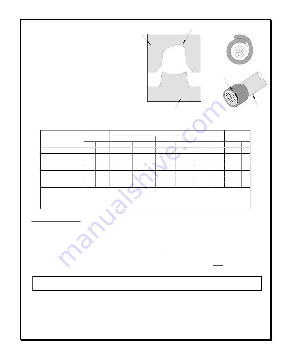
Insulation Crimp Note
:
Due to the terminal’s insulation grip design
and/or insulation diameter range, this tool
uses “overlap” form geometry in the
insulation punch. This produces an overlap
insulation crimp (A620 – compliant). While
the insulation punch profile may appear
“lopsided”, this is a normal condition for this
tool. See figure to the right. (Some tools with
multiple crimp pockets may not have the
“overlap” profile on all pockets).
CONDITIONS:
After crimping, the conductor profiles should
measure the following (See notes below).
Terminal Series No.
Wire Size
Conductor
Pull Force
Minimum
Profile
Crimp Height (Ref)
Crimp Width (Ref)
AWG mm
2
mm
In.
mm
In.
N
Lb.
A
B
C
43178
18
0.80
1.78-1.88
.070-.074
3.20
.126
88.9
20.0
X
43374
14
2.09
1.65-1.75
.065-.069
2.50
.098
222.4
50.0
X
16
1.33
1.38-1.48
.054-.058
2.50
.098
133.4
30.0
X
18
0.82
1.35-1.43
.053-.056
2.50
.098
88.9
20.0
X
43375
14
2.09
1.65-1.75
.065-.069
2.50
.098
222.4
50.0
X
16
1.33
1.38-1.48
.054-.058
2.50
.098
133.4
30.0
X
18
0.82
1.35-1.43
.053-.056
2.50
.098
88.9
20.0
X
To Achieve IPC-A-620 Class 2 Crimps, the following over-all wire insulation diameter ranges are recommended:
1.
Profile A: 2.36-3.56mm (.093-.140 inch)
2.
Profile B: 2.79-3.56mm (.110-.140 inch)
3.
Profile C: 2.36-3.14mm (.093-.124 inch)
Tool Qualification Notes:
1. Pull Force should be measured with no influence from the insulation crimp.
2. The above specifications are guidelines to an optimum crimp.
Note:
A crimp height chart is provided with this manual as Reference Only. Due to the wide range of wires, strands,
insulation diameters, and durometers, actual crimp height measurements may very slightly. An occasional,
destructive, pull force test should be preformed to check hand tool crimp. Pull Force value must exceed the
minimum pull force specifications listed.
CAUTION:
Install only Molex terminals listed above with this tool. Do not crimp hardened objects as damage
can occur to the tool or die.
INSTALLATION
To install the Tool Kit into the Power Crimp Head follow the steps below:
Anvils and Punches Installation
1.
Insert the Anvils into the bottom slots of the nest. Install the M4 x 10 long BHCS and tighten in place.
OVERLAP
INSULATION
CRIMP
OVERLAP FORM GEOMETRY
ANVIL
PUNCH
WIRE


