


Hand Crimp Tool For
3.50 (.138”) Wire to Wire Connector, Crimp Pin
Doc No: ATS 638238700
Release Date: 07 13 11
Page 2 of 7
Revision: A
Revision Date: 07 13 11
5
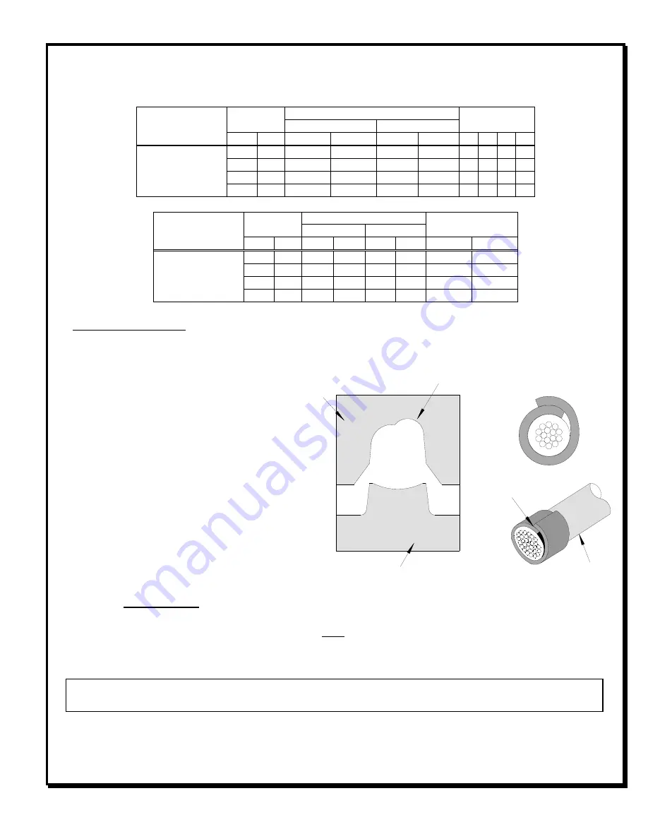
After crimping, the conductor profile should measure the following.
!,
! -
#
!
.
"/
!
!
! ,
! ,
" 0
2
,,
'
,,
#
,,
#
1& '* '' '4
50419
18
0.87 1.18 1.28 .046 .050
1.75
.069
X
20
0.50 1.05 1.15 .041 .045
1.75
.069
X
22
0.35 0.95 1.04 .037 .041
1.75
.069
X
24
0.20 0.90 0.99 .035 .039
1.75
.069
X
!,
! -
#
!
.
-/
0
2
/ + !
,/,
! ,
! ,
"
,,
'
,,
#
,,
#
6#
50419
18
0.87
2.75
.108
2.40
.094
88.2
19.8
20
0.50
2.55
.100
2.40
.094
58.8
13.2
22
0.35
2.40
.094
2.40
.094
39.2
8.8
24
0.20
2.30
.091
2.40
.094
29.4
6.6
Tool Qualification Notes:
1. Pull Force should be measured with no influence from the insulation crimp.
2. The above specifications are guidelines to an optimum crimp.
▲
-/
! ,
:
Due to the terminal’s insulation grip design
and/or insulation diameter range, this tool
uses “overlap” form geometry in the
insulation punch. This produces an overlap
insulation crimp (A620 – compliant). While
the insulation punch profile may appear
“lopsided”, this is a normal condition for this
tool. See figure to the right. (Some tools with
multiple crimp pockets may not have the
“overlap” profile on all pockets).
5
A crimp height chart is provided with this
manual as Reference Only. Due to the wide range of wires, strands, insulation diameters, and durometers
available, actual crimp height measurements may very slightly. An occasional, destructive, pull force test should be
performed to check hand tool crimp. Pull Force value Must exceed the Minimum pull force specifications listed.
5
Install only Molex terminals listed above with this tool. Do not crimp hardened objects as damage can
occur to the tool or die.
Open the tool by squeezing the handles together. At the end of the closing stroke, the ratchet mechanism will
release the handles and the hand tool will spring open. See Figure 1.
7
+
8
+
8


