background image

Tool Kit for CSP 6.3 Receptacle Terminal 

Doc No: ATS-6382557HM  Release Date: 07-31-12 

UNCONTROLLED COPY


Page 2 of 8 

Revision: A 

Revision Date: 07-31-12 


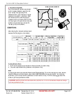
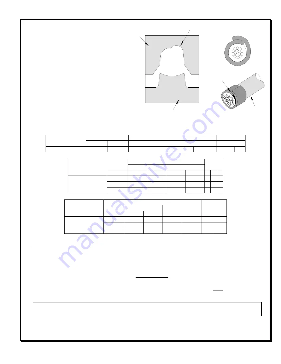
Insulation Crimp Note

Due to the terminal’s insulation grip design 
and/or insulation diameter range, this tool 
uses “overlap” form geometry in the 
insulation punch. This produces an overlap 
insulation crimp (A620 – compliant). While 
the insulation punch profile may appear 
“lopsided”, this is a normal condition for this 
tool. See figure to the right. (Some tools with 
multiple crimp pockets may not have the 
“overlap” profile on all pockets). 
 

CONDITIONS: 

 
After crimping, the conductor profiles should 
measure the following (see notes below). 
 

Terminal Series No. 

Bell mouth 

Conductor Brush 

Bend up    Bend Down 

Twist   Roll 

mm 

In. 

mm 

In. 

Degree (Max) 

Degree (Max) 

98891 

0.40-0.80  .015-.030  0.20-1.80  .008-.070 

10 


Terminal Series No. 

Wire Size 

Conductor Crimp 

Profile 

Height 

Width 

mm

2


mm 

In. 

mm 

In. 

A  B  C 

98891 

1.00 

1.77-1.83  .070-.072  2.78-2.84  .109-.112  X   


2.00 

2.02-2.08  .080-.082  2.78-2.84  .109-.112


  X   

2.50 

2.12-2.18  .083-.086  2.78-2.84  .109-.112


  X 


Terminal Series No. 

Wire Size 

Insulation Crimp 

Pull Force 

Minimum 

Height 

Width Maximum 

mm

2


mm 

In. 

mm 

In. 

Lb. 

98891 

1.00 

2.50-2.70  .098-.106  4.41-4.61  .174-.181  120.0  26.96 

2.00 

2.95-3.15  .116-.124  4.41-4.61  .174-.181  180.0  40.44 

2.50 

3.20-3.40  .126-.134  4.41-4.61  .174-.181  210.0  47.19 

 
Tool Qualification Notes: 
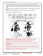
1.  Pull Force should be measured with no influence from the insulation crimp. 
2.  The above specifications are guidelines to an optimum crimp. 
 

Note:


A crimp height chart is provided with this manual as Reference Only.  Due to the wide range of wires, strands, 
insulation diameters, and durometers, actual crimp height measurements may very slightly.  An occasional, 
destructive, pull force test should be preformed to check hand tool crimp.  Pull Force value must exceed the 
minimum pull force specifications listed. 


CAUTION: 

Install only Molex terminals listed above with this tool.  Do not crimp hardened objects as damage 

can occur to the tool or die. 

OVERLAP 

INSULATION 

CRIMP 

OVERLAP FORM GEOMETRY 

ANVIL 

PUNCH 

WIRE 

Summary of Contents for 63825-5700

Page 1: ... handling due to outstanding force ratio Tool kits are easily installed into the Hand Crimp Tool or the 63816 0300 Power Crimp Head which is installed into the 63816 0200 110 V or the 63816 0250 220 V Battery Powered Tool Many different Tool kits can be used with a single Battery Powered Tool This tool is IPC WHMA A 620 Class 2 and RoHS compliant SCOPE Products CSP 6 3 Receptacle Terminal 1 00mm 2...

Page 2: ... 1 00 1 77 1 83 070 072 2 78 2 84 109 112 X 2 00 2 02 2 08 080 082 2 78 2 84 109 112 X 2 50 2 12 2 18 083 086 2 78 2 84 109 112 X Terminal Series No Wire Size Insulation Crimp Pull Force Minimum Height Width Maximum mm2 mm In mm In N Lb 98891 1 00 2 50 2 70 098 106 4 41 4 61 174 181 120 0 26 96 2 00 2 95 3 15 116 124 4 41 4 61 174 181 180 0 40 44 2 50 3 20 3 40 126 134 4 41 4 61 174 181 210 0 47 1...

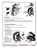
Page 3: ...all the M4 x 10 long BHCS and tighten in place 2 Insert the Punches into the top slots of the nest Install the M4 x 18 long BHCS and tighten in place See Figure 1 Locator Installation and Removal Follow the steps below to install or replace the locator See Figure 2 To install the locator 1 Position the locator with the hole over the brass pivot shaft and snap it into place To remove the locator 1 ...

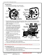
Page 4: ... its original position 6 Turn the Locator Lock Latch up to lock Make sure that the terminal is visually centered over the punch 7 Insert the proper wire over the terminal 8 Gently touch the wire stop with the end of the wire See Figure 6 and 7 9 Compress the terminal by squeezing the tool handles until the ratchet mechanism cycle has been completed Release handles to open the jaws 10 Remove the cr...

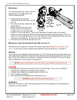
Page 5: ...ially closed position Do Not force the handles open or closed The tool will open easily by rotating the small slotted screw marked with an arrow See Figure 11 Warranty This tool kit is for electrical terminal crimping purposes only This tool kit is made of the best quality materials All vital components are long life tested All tools are warranted to be free of manufacturing defects for a period o...

Page 6: ...No Adapter Description Figure No 63825 5770 63810 1050 Hand Crimp Frame Short N A N A 9 63810 1000 Hand Crimp Frame Long N A N A 9 63816 0200 Battery Power Tool 110 V 63816 0300 Power Crimp Head 10 63816 0250 Battery Power Tool 220 V 63816 0300 Power Crimp Head 10 Applications for the Tool Kit Hand Crimp Tool Battery Powered Tool Figure 9 Figure 10 WARNING NEVER operate service install tool kits o...

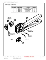
Page 7: ...te 07 31 12 RATCHET RELEASE SCREW Figure 11 M4 X 8mm LONG BHCS 2 1 3 M4 X 18mm LONG BHCS M4 X 10mm LONG BHCS 2 4 WITH TOOL KIT LOCATOR ONLY HAND TOOL PARTS LIST Item Number Order Number Description Quantity 1 63810 1000 Hand Crimp Frame Long 1 2 63825 5770 Tool Kit with Locator 1 3 63823 0573 Locator Base 1 4 63825 5775 Locator only REF ...

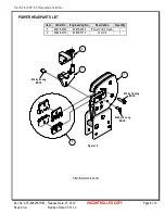
Page 8: ...ED COPY Page 8 of 8 Revision A Revision Date 07 31 12 Figure 12 1 2 2 M4 by 8 Long BHCS M4 by 18 Long BHCS M4 by 10 Long BHCS 1 POWER HEAD PARTS LIST Item Order No Engineering No Description Quantity 1 63816 0300 63816 0300 Power Crimp Head 1 2 63825 5770 63825 5770 Tool Kit 1 http www molex com ...

Reviews: