Hand Crimp Tool for 1.50mm (.059") Pico-SPOX Crimp Terminals
Doc. No: ATS-6382597HM Release Date: 05-06-13
UNCONTROLLED COPY
Page 2 of 6
Revision: B
Revision Date: 04-26-18
▲
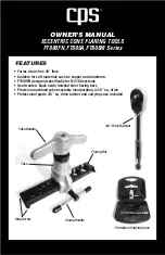
Insulation Crimp Note
Due to the terminal’s insulation grip design and
insulation diameter range, this tool uses the
overlap
form geometry in the insulation punch.
This produces an overlap insulation crimp (A-620-
compliant). Although the insulation punch profile
may appear lopsided, this is a normal condition
for this tool. See figure to the right. Some tools
with multiple crimp pockets may not have the
overlap profile on all pockets.
CRIMP SPECIFICATIONS
Terminal Series
No.
Bell Mouth
Conductor Brush
Bend Up Bend Down Twist
Roll
mm
In.
mm
In.
Degree
Degree
87421
0.05-0.40 .002-.016 0.00-0.50 .000-.020
3
3
3
3
After crimping, the crimp profiles should measure the following:
Terminal
Series No.
Wire Size
Conductor Crimp
Insulation Crimp
Pull Force
Minimum
Profile
Height (Ref.)
Width (Ref.) Height (Ref.) Width (Ref.)
AWG mm
2
mm
In.
mm
In.
mm
In.
mm
In.
N
Lb.
24 26-30
87421
24
0.20 0.56-0.60 .022-.024 1.00
.039
1.40
.055
1.10
.043 29.4 6.60
X
26
0.12 0.52-0.58 .020-.023 1.00
.039
1.24
.049
1.10
.043 19.6 4.40
X
28
†
30
†
To achieve IPC/WHMA-A-620 class 2 crimps, the following overall wire insulation diameter ranges are recommended:
Profile 24:
0.90-1.15mm (.035-.045”)
Profile 26-30:
0.80-1.00mm (.032-.040”)
†
Scope Change:
As of 06-15-2017, Molex Product Engineering does not recommend the use of 28 AWG and 30 AWG
wires in 87421-000* terminals. Terminal 87421-010* should be used for 28 AWG and 30 AWG wires. See the Molex website
for appropriate application tooling.
Tool Qualification Notes
1.
(Ref) means the dimension provided is approximate due to the wide range of wires, conductor
stranding, insulation diameters and insulation hardness.
2.
An occasional pull force test should be performed. It must exceed the minimum pull force
specification.
3.
Pull force should be measured with no influence from the insulation crimp. To ensure this, strip
the wire long enough so the terminal insulation grips do not contact the wire insulation.
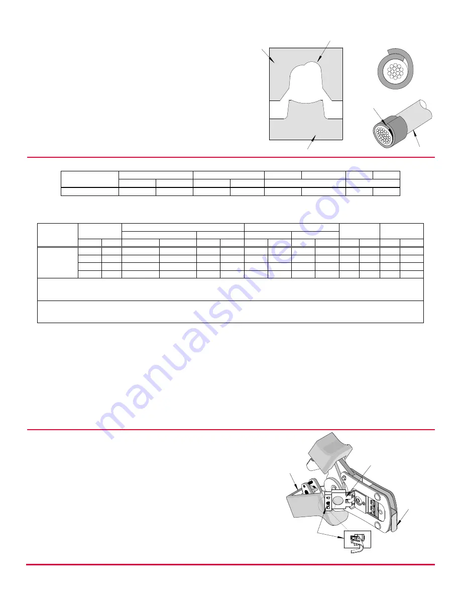
OPERATION
Open the tool by squeezing the handles together. At the
end of the closing stroke, the ratchet mechanism will
release the handles, and the hand tool will spring open.
1.
With the hand tool in the open position, pivot the
terminal locator open by pulling on the locator knob,
and lift the wire stop blade up. See Figure 1.
2.
Insert the terminal into the correct profile until the
terminal is fully seated and stops.
3.
Gently pivot the locator closed.
4.
Bring down the wire stop blade. Make sure the wire
stop blade is fully seated on the terminal behind the
conductor grip section.
TERMINAL
SEATED IN
LOCATOR
SWING
LOCATOR
OPEN
Figure 1
HAND TOOL
OPEN
WIRE
STOP BLADE
OVERLAP
INSULATION
CRIMP
OVERLAP FORM GEOMETRY
ANVIL
PUNCH
WIRE