background image

Hand Tool for Appli-Mate RAST Power Connectors 

Doc No: ATS-6382762HM 

Release Date: 10-27-14 

UNCONTROLLED COPY


Page 4 of 7 

Revision: A 

Revision Date: 10-27-14 

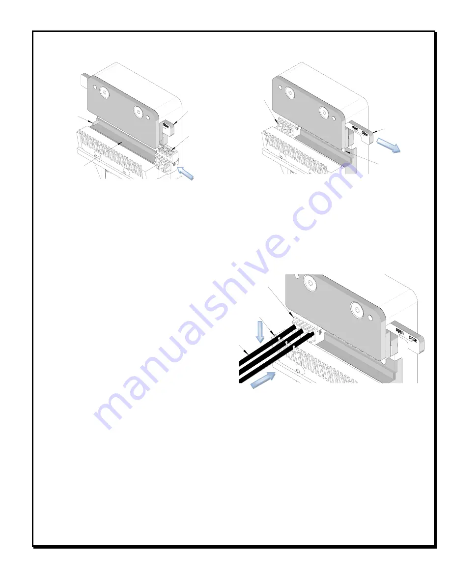
ORIENT THE 

SLOT ON TOP 

Figure 4 

CONNECTOR 

IN PLACE 

TOOL NEST 

CONNECTOR 

STOP 

BAR CLOSED 

TERMINATION 

BLADES DOWN 

BAR OPEN 

PUSH WIRE INTO CONNECTOR 

PRESS WIRE 

DOWN INTO COMB 

Figure 5 

CONNECTOR 

RETAINING COMB 


OPERATION 


1.


Open the tool by squeezing the handles together, at the end of the closing stroke, the ratchet mechanism 
will release the handles, and the hand tool will spring open. 

2.


Before loading the connector in the tool, make sure the termination blade is raised (see Termination 
Blade Position). 

3.


With the hand tool in the open position, load the connector in the tool. The tool nest is polarized to accept 
the connector in only one orientation (tabs facing outward) See Figure 4. 

4.


Push the connector all the way to the left until it stops. 

5.


Lower the termination blade by pulling the bar away from the tool. 


NOTE

: If the termination blade is not 

lowered, the connector will not be 
completely terminated. 

 
6.


Place the wire into the 
connector, pushing it in until it 
stops against the back of the 

connector housing. 

7.


To keep the wire in place, press 
it into the retaining comb on the 

front of the tool. See Figure 5. 

8.


Repeat steps 6 and 7 until all 
wires are loaded into the 
connector. 

9.


To terminate the connector, squeeze the tool handles together until the anti-backup ratchet releases. 
Release the handles and they will spring open. 

10.


Push in the bar to raise the termination blade. 
 

NOTE

: If the termination blade is not raised, it will be difficult to remove the connector from the tool. 

 
11.


Lift all wires out of the retaining comb and pull the finished connector out of the tool. 


NOTE:

 The tamper proof ratchet action will not release the tool until it has been fully closed. 

Summary of Contents for 63827-6200

Page 1: ...ires for these products Connector Series No Circuit Size Connector Assembly Order No 91627 2 91627 0001 91627 0002 91627 0003 91627 0004 91627 0005 91627 0006 91627 0008 91627 0009 91627 0010 91627 0011 91627 0012 91627 0013 91627 0014 91627 0015 91627 0016 91627 0501 91627 0502 91627 0503 91627 0504 91627 0505 91627 0506 91627 0507 91627 0508 3 91627 1001 91627 1002 91627 1004 91627 1005 91627 10...

Page 2: ...1 93211 1002 93211 1003 93211 1004 93211 1501 93211 1503 4 93211 2001 93211 2501 93211 2502 5 93211 3001 93211 3501 6 93211 4001 93211 4501 93211 4502 93211 4503 7 93211 5001 93211 5501 93211 5502 8 93211 6001 93211 6501 9 93211 7001 93211 7501 93211 7502 10 93211 8001 93211 8501 11 93211 9001 93211 9251 12 93211 9501 93211 9751 93322 2 93322 0001 93322 0501 3 93322 1001 93322 1002 93322 1501 4 93...

Page 3: ... crimp tooling is damaged or worn a new tool must be purchased 4 Terminated height should be used as the final criteria for an acceptable crimp Pull force is a reference only 5 Molex does not certify crimp hand tools SETUP Connector Preparation Trim one connector off the molded chain using a razor blade as shown below See Figure 2 When trimming the connector off the molded chain be careful to not ...

Page 4: ...ing outward See Figure 4 4 Push the connector all the way to the left until it stops 5 Lower the termination blade by pulling the bar away from the tool NOTE If the termination blade is not lowered the connector will not be completely terminated 6 Place the wire into the connector pushing it in until it stops against the back of the connector housing 7 To keep the wire in place press it into the r...

Page 5: ...sed to prevent objects from becoming lodged in the nest and store the tool in a clean dry area Miscrimps or Jams Should this tool ever become stuck or jammed in a partially closed position Do Not force the handles open or closed The tool will open easily by lifting the ratchet release lever See Figure 8 Warranty This tool is for electrical connector termination purposes only This tool is made of t...

Page 6: ...e injury CAUTION Wear safety glasses when operating or servicing this tool The chart below shows all applications for this Modular Crimp Head Modular Crimp Head Order No Tool Order no Tool Description Adapter Order No Adapter Description Figure No 63827 6270 63816 0000 Hand Crimp Frame Short N A N A 5 63816 0050 Hand Crimp Frame Long N A N A 5 63816 0200 Battery Power Tool 110 V 63816 0600 Battery...

Page 7: ...A Revision Date 10 27 14 RATCHET RELEASE LEVER HANDLE SPRING 2 1 5 Figure 8 3 4 2 PARTS LIST Item Order Number Description Quantity 1 63827 6270 Modular Crimp Head 1 2 63816 0050 Hand Crimp Frame Long 1 3 63816 0001 Locking Pin 2 4 63600 0520 Tool Head Spring 2 5 63600 0525 Handle Spring 1 Visit our Web site at http www molex com ...

Reviews: