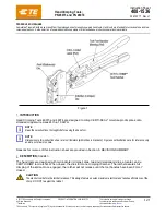
Air Head Crimp Tool for InsulKrimp™ Piggyback QD
Doc. No: ATS-640056200
Release Date: 09-19-06
UNCONTROLLED COPY
Page 2 of 7
Revision: C
Revision Date: 10-07-14
Wire Size: 10 – 12 AWG 5.00 – 3.30mm²
Terminal No. Terminal Eng. No. (REF) Terminal No. Mylar Tape
Wire Strip Length
Insulation Diameter
Maximum
In
mm
In.
mm
19011-0007
C-2303
19011-0008
.380
9.53
.260
6.48
Wire Size: 14 – 16 AWG 2.00 – 1.30mm²
Terminal No. Terminal Eng. No. (REF) Terminal No. Mylar Tape
Wire Strip Length Insulation Diameter
Maximum
In.
mm
In.
mm
19011-0004
BB-2302
19011-0006
.310
7.94
.150
3.68
19011-0037
19011-0037
19011-0038
.310
7.94
.140
3.56
Wire Size: 18 – 22 AWG 0.80 – 0.35mm²
Terminal No. Terminal Eng. No. (REF) Terminal No. Mylar Tape
Wire Strip Length
Insulation Diameter
Maximum
In.
mm
In.
mm
19011-0001
AA-2301
19011-0003
.310
7.94
.140
3.56
19011-0035
19011-0035
19011-0036
.310
7.94
.110
2.79
OPERATION
Refer to the instruction manual for the 19279-0001 (AT-200)
for mounting this crimp tool head.
Crimping Terminals
1.
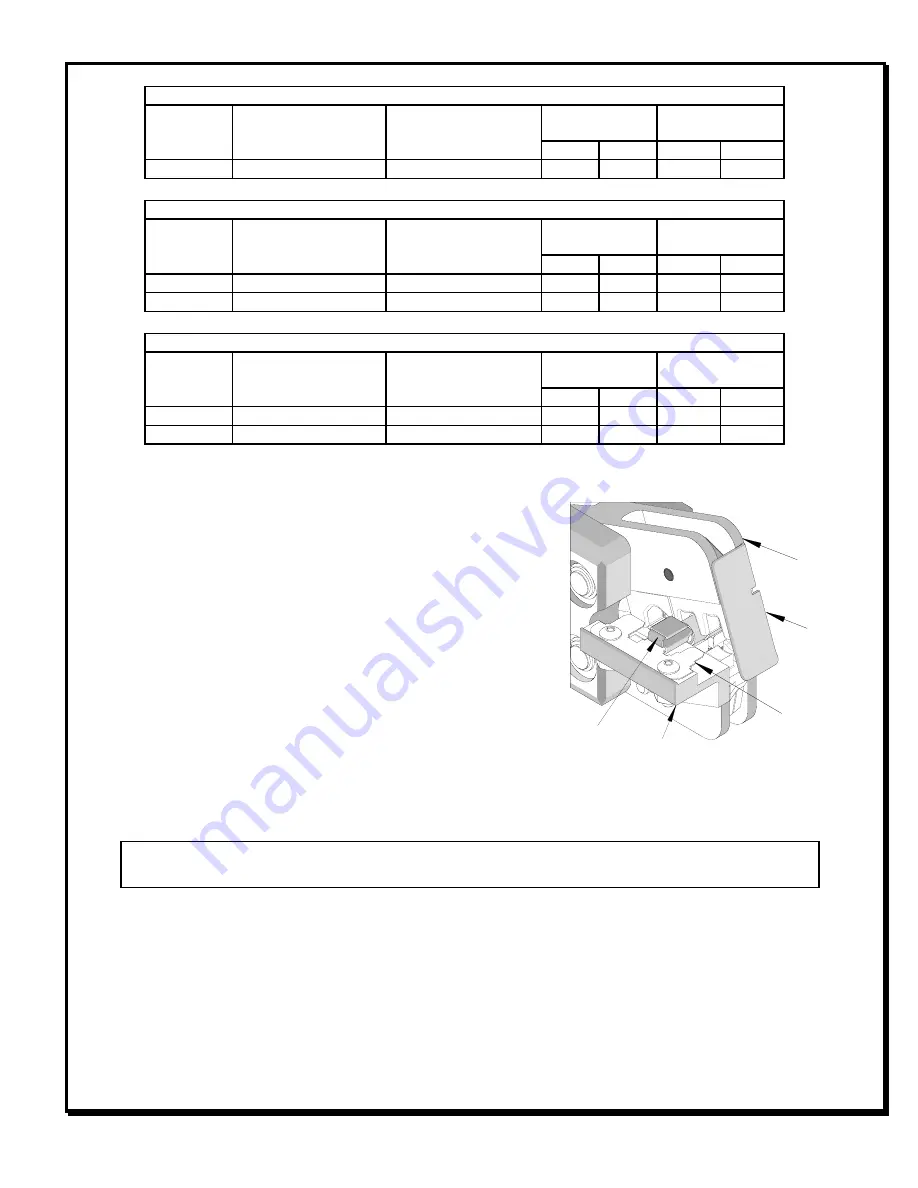
Push the terminal onto the tab locator all the way to the
stop in the proper color-coded nest. The male tab of the
terminal should be up. See Figure 1.
2.
The height of the locator may need to be adjusted when
changing from one terminal size to another. To do this,
loosen the locator lock nut, (See Figure 3), and adjust
height so the tab aligns with the female locator tab.
Tighten the lock nut.
3.
Insert the wire into the terminal. Push the terminal and wire onto the tab locator all the way to the stop in
the proper color-coded nest. The barrel of the terminal should be up. See Figure 2.
CAUTION:
Never operate this tool without the supplied safety shield in place. Never place fingers in the
tool nests.
4.
Push on the wire to assure it is still fully seated in the terminal. The wires end should butt against the wire
stop stamped into each terminal. See Figure 2 and 3. Cycle the tool.
MALE TAB
FACING UP
SAFETY
SHIELD
TAB LOCATOR
Figure 1
LOCATOR
JAWS
OPEN


