
AT2080 Air Crimp Tool Head
Doc No: ATS-640052500
Release Date: 01-20-03
UNCONTROLLED COPY
Page 4 of 7
Revision: C
Revision Date: 06-23-21
MAINTENANCE
It is recommended that each operator of the tool be made aware of and responsible for the
following maintenance steps:
1.
Remove dust, moisture and other contaminants with a
clean brush or a soft, lint-free cloth.
2.
Do not use any abrasive materials that could damage
the tool.
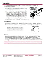
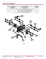
3.
Make certain all pins, pivot points and bearing surfaces
are protected with a thin coat of high-quality machine
oil. Do not oil excessively. This tool was engineered for
durability, but like any fine piece of equipment, it needs
cleaning and lubrication for a maximum service life of
trouble-free crimping. Using a light oil such as 30
weight automotive oil at the oil points shown in Figure 4
every 5,000 crimps or monthly will significantly enhance
the tool life and ensure a stable calibration.
4.
When the tool is not in use, store the tool in a clean, dry area.
Tool Calibration
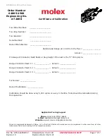
A Certificate of Calibration (see last page) was supplied with the tool. To recalibrate this tool, pin
gauge measurements should be taken in each conductor nest and compared to this chart. The tool
should be lubricated prior to recalibration to ensure consistent measurements.
Warranty
This tool is for electrical terminal crimping purposes only. This tool is made of the best quality
materials. All vital components are long-life tested. All tools are warranted to be free of
manufacturing defects for a period of 30 days. Should such a defect occur, Molex would repair or
exchange the tool free of charge. This repair or exchange will not be applicable to altered, misused
or damaged tools.
CAUTION: Molex crimp specifications are valid only when used with Molex terminals, applicators
and tooling.
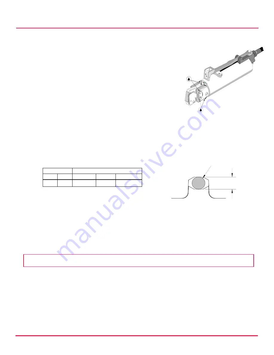
Wire Range
“X” Dimension Conductor Crimp
AWG mm²
Mean
Go
No-Go
8
8.50
.140
.136
.146
PIN GAUGE IN
CONDUCTOR CRIMP
“Confining” Crimp
X
LUBRICATION POINTS
(BOTH SIDES)
LIGHT OIL (EVERY MONTH
OR 5,000 CRIMPS)
Figure 4


