background image

AT2080 Air Crimp Tool Head 

Doc No: ATS-640052500 

Release Date: 01-20-03 

UNCONTROLLED COPY


Page 5 of 7 

Revision: C 

Revision Date: 06-23-21 

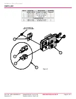
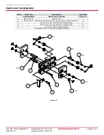
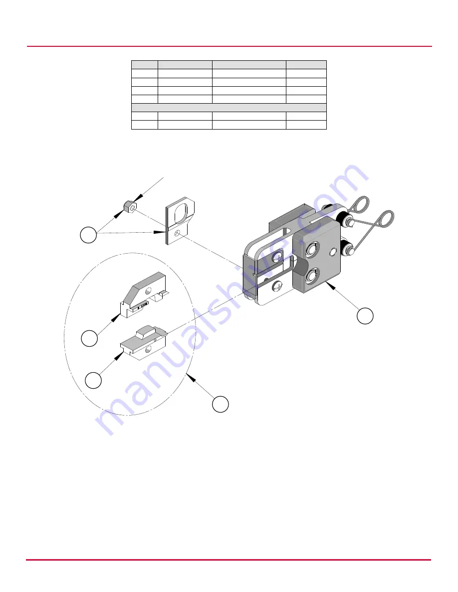
Figure 5 

M4 LOCKNUT W/ 

HEX NYLON INSERT 

PARTS LIST 


Item 

Order No. 

Description 

Quantity 


64005-2500  Crimp Tool Head  Figure 5 

64005-0000  Basic Air Tool Head  

64001-2575 

Locator Assembly 

64001-2570 

Tooling Kit 

Tooling Kit Only 

64001-2501 

Conductor Punch 

64001-2502 

Conductor Anvil 


Summary of Contents for AT 2080

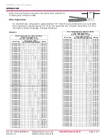
Page 1: ... intended for use in the 19279 0001 AT 200 either handheld or with optional bench adapter 19078 0307 ATBA and foot switch Wire Size 8 AWG 8 50mm Terminal Order No Terminal Engineering No Ref Wire Strip Length Wire Combinations mm In 19160 0024 NC 8 Varies Varies See Chart 1 19160 0144 NC 8 Varies Varies See Chart 1 Testing Mechanical The tensile test or pull test is a means of evaluating the mecha...

Page 2: ...tranded only 5 UL CSA Stranded only 4 UL CSA Stranded only 4 2 UL CSA Stranded only 4 1 UL CSA Stranded only 3 UL CSA Stranded only 3 3 UL CSA Stranded only 3 2 UL CSA Stranded Only 3 1 UL only Stranded only 3 5 UL CSA Stranded only 3 4 UL CSA Stranded only 3 3 UL CSA Stranded only 3 2 UL CSA Stranded only 3 1 UL CSA Wire Combinations for Nylon Insulated Closed End Connectors Part No 191600024 NC ...

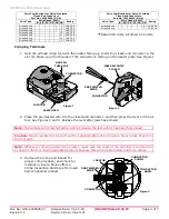
Page 3: ...old the airhead crimp tool with the locator facing up Insert the closed end connector in the slot 8 Make sure the shoulder of the connector is resting on the locator plate See Figure 1 2 Place the pre twisted wire into the closed end connector and then press the lever on the air tool See Figures 2 and 3 Release the lever after jaws have closed Note The tamper proof ratchet action will not release ...

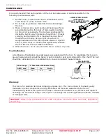
Page 4: ... a stable calibration 4 When the tool is not in use store the tool in a clean dry area Tool Calibration A Certificate of Calibration see last page was supplied with the tool To recalibrate this tool pin gauge measurements should be taken in each conductor nest and compared to this chart The tool should be lubricated prior to recalibration to ensure consistent measurements Warranty This tool is for...

Page 5: ...n Date 06 23 21 2 3 1 Figure 5 M4 LOCKNUT W HEX NYLON INSERT 4 5 PARTS LIST Item Order No Description Quantity 64005 2500 Crimp Tool Head Figure 5 1 64005 0000 Basic Air Tool Head 1 2 64001 2575 Locator Assembly 1 3 64001 2570 Tooling Kit 1 Tooling Kit Only 4 64001 2501 Conductor Punch 1 5 64001 2502 Conductor Anvil 1 ...

Page 6: ... 2 4 2 2 2 2 2 PARTS LIST CONTINUED Item Order No Description Quantity 64005 0000 Basic Air Tool Head Figure 6 1 64005 0103 Nose Guard 1 2 64000 0077 Repair Kit Springs Rods Pivots Rings and Washers 1 3 M4 by 12 Long Freedrive Pan Head Screw 1 4 M4 by 30 Long Freedrive Pan Head Screw 1 5 3 16 by 3 8 Long Dowel Pin 1 Available from an industrial supply company ...

Page 7: ...Range Conductor Nest 1 ____________ Actual ______________ Range Conductor Nest 2 ____________ Actual ______________ Range Conductor Nest 3 ____________ Actual ______________ Technician ______________ Date of Calibration ______________ Calibration should be done every 5 000 cycles or every 3 months Tools should be lubricated during this operation Application Tooling Support Phone 402 458 TOOL 8665 ...

Reviews: