CS 150 Battery Crimping Tool
Doc No: ATS-638160200
Release Date: 12-06-07
UNCONTROLLED COPY
Page 9 of 21
Revision: A
Revision Date: 12-06-07
3.1 Set-Up
Before starting any work on electrical applications make sure there are no
live cables or parts in the immediate area of the user.
WARNING
Remove the battery from the crimping tool before
installing and removing dies in the crimp head.
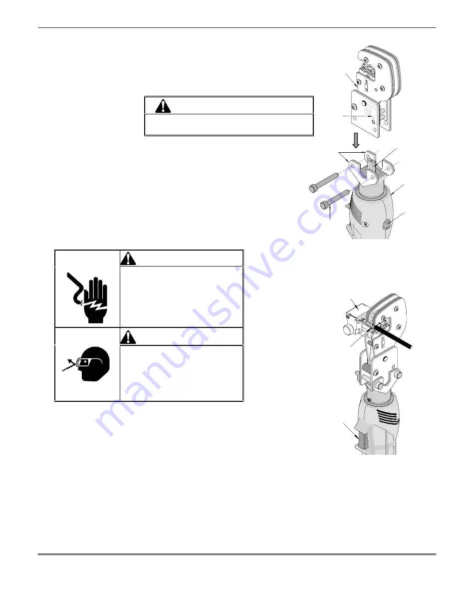
1. Select the appropriate crimping head with the proper tooling kit
inserted for the application needed.
2. Remove the locking pins (2) from the adapter plate on the crimping
tool.
3. Place the crimping head into the adapter and push down until it
engages into the slot of the adapter.
4. Replace the locking pins (2) making sure the crimping head is secure.
The locking pins can be inserted from either side of the adapter plate.
See Figure 3-1.
WARNING
Electric shock hazard:
This tool is not insulated. When using this
unit near energized electrical lines, use
proper personal protective equipment.
Failure to observe this warning could
Result in severe injury or death.
WARNING
Wear eye protection when operating
or servicing this tool.
Failure to wear eye protection could
result in serious eye injury from flying
debris or hydraulic oil.
3.2 Operation
1. Insert the proper terminal or connector into the tooling nest and push on the
trigger in the handle just enough so the dies contact the terminal or connector
securely. Release the trigger. This allows the operator to make adjustments
to the connector before the final termination.
2. Insert the wire or cable into the terminal. Push on the wire or cable to assure it is fully seated in the
terminal.
3. Hold the trigger down again until the crimping tool achieves pressure relief, which is accompanied by an
audible “pop”.
Figure 3-2
WITH LOCATOR
HOLD
TRIGGER
DOWN
TERMINAL
AND WIRE
IN PLACE
Figure 3-1
LOCKING
PINS (2)
CRIMPING
TOOL
CRIMPING
HEAD
ADAPTER
CRIMPING
HEAD WITH
TOOLING
ADAPTER
PLATES
LOCKING
LATCH
RETRACT
SLIDE


