background image

RHT-4754 Hand Crimp Tool 

Doc No. 64003-7200 

Release Date: 08-02-06 

UNCONTROLLED 

COPY


Page 2 of 7 

Revision: A 

Revision Date: 08-02-06 

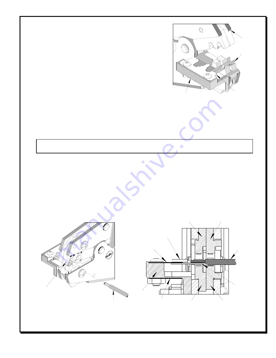
Figure 3 

2

ND

 TAB 

LOCATOR 

WIRE 

TERMINA

BARREL 

INSULATIO

PUNCH 

CONDUCTOR 

ANVIL 

TERMINA

LOCATO

CONDUCTO

PUNCH 

INSULATION 

ANVIL 

1

ST 

TAB 

LOCATOR 

Figure 2 

TERMINAL 

WIRE 


OPERATION 

 
Open the tool by first closing the jaws sufficiently for the 
ratchet mechanism to release. 
 

Crimping Terminals 

 
1.  There are 2 Tab Locator Blades supplied with the 

tool.  One is for .187 and .250 Tabs; the other is for 
.205 Tabs and .110 Tabs.  Make sure the proper 
blade is installed on the top of the locator and the 
other is stored on the bottom of the locator. 

2.  Push the terminal onto the tab locator all the way to 

the stop in the nest.  The barrel of the terminal should be up.  See Figure 1. 

3.  Partially close the tool to hold the terminal in place.  See Figure 2. 
4.  Insert the properly stripped wire into the terminal barrel.  See Figure 2 and 3.  Cycle the 

tool. 
 

Note:

  The tamper proof ratchet action will not release the tool until it has been fully 

closed. 

 
5.  Remove the crimp and inspect for proper crimp location, and check for insulation closure.  

Molex offers a Crimp Inspection Handbook for closed barrel industrial product.  See our 
website or contact your sales engineer. 

6.  If the insulation part of the crimp needs to be adjusted, first loosen the M4 screw on the 

bottom tool jaw, then insert a 3/32 hex wrench (supplied) into the bottom of the lower die.  
See Figure 4.  A clockwise (CW) rotation decreases insulation crimp while a counter-
clockwise (CCW) rotation increases insulation crimp.  After adjusting retighten the M4 
screw. 


LOCATOR 

JAWS 
OPEN 

TAB 

LOCATOR 

Figure 1 

TERMINA

Summary of Contents for RHT-4754

Page 1: ...following charts show the UL specifications for various wire sizes The tensile strength is shown in pounds and indicates the minimum acceptable force to break or separate the terminal from the conductor Wire Size AWG UL 310 22 8 20 13 18 20 16 30 14 50 UL 310 Quick Disconnects The following is a partial list of the product part numbers and their specifications that this tool is designed to run We ...

Page 2: ...the nest The barrel of the terminal should be up See Figure 1 3 Partially close the tool to hold the terminal in place See Figure 2 4 Insert the properly stripped wire into the terminal barrel See Figure 2 and 3 Cycle the tool Note The tamper proof ratchet action will not release the tool until it has been fully closed 5 Remove the crimp and inspect for proper crimp location and check for insulati...

Page 3: ...e keep the handles closed to prevent objects from becoming lodged in the crimping dies and store the tool in a clean dry area Miscrimps or Jams Should this tool ever become stuck or jammed in a partially closed position Do Not force the handles open or closed The tool will open easily by pressing the ratchet release lever See Figure 5 How To Adjust Tool Preload See Figure 5 Over the life of the to...

Page 4: ...Tool Doc No 64003 7200 Release Date 08 02 06 UNCONTROLLED COPY Page 4 of 7 Revision A Revision Date 08 02 06 5 Replace the plastic cover washer and screw 6 Check the crimp specifications after tool crimp force is adjusted ...

Page 5: ... Code Wire Range X Dimension Conductor Crimp Awg mm Mean Go No Go Red 22 18 0 35 0 80 052 049 060 Blue 16 14 1 30 2 00 061 058 069 CAUTION Repetitive use of this tool should be avoided Warranty This tool is for electrical terminal crimping purposes only This tool is made of the best quality materials All vital components are long life tested All tools are warranted to be free of manufacturing defe...

Page 6: ...S REQUIRED FOR REPAIR ONLY MAIN SPRING SHOWN 2 PARTS LIST Item Order No Description Quantity 64003 7200 Hand Crimp Tool Fig 6 1 64000 0076 Repair Kit Springs Pins and E Rings 1 2 63810 0000 Handle 1 3 64003 1175 Locator Assembly 1 4 64003 7270 Tooling Kit 1 Tooling Kit Only 5 64003 7202 Conductor Punch 1 6 64003 7201 Conductor Anvil 1 7 64003 7204 Insulation Punch 1 8 64003 7203 Insulation Anvil 1...

Page 7: ... Conductor Nest 1 ____________ Actual ______________ Range Conductor Nest 2 ____________ Actual ______________ Technician______________ Date of Calibration ______________ Calibration should be done every 5 000 cycles or 3 months Tools should be lubricated during this operation mericas Headquarters e Illinois 60532 U S A 00 78MOLEX erinfo molex com Far East North Headquarters Yamato Kanagawa Japan ...

Reviews: