Parameterisation manual
Manual No.:
MWF-PA102
Microwave level measurement
MWF
Index
0
Date
08.08.18
Adaption of parameters with the MWF2-KIT
Page 5 of 9
Line 14 and 15
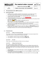
Setting of upper dead band [TB]
Dependent on the installation situation of the MWF signal disturbances could occur in the upper area of
the measuring probe (e.g. caused by a narrow nozzles). In order to suppress these disturbances, an
upper dead band can be determined. Within the entered length, starting from the reference point [R], the
measuring probe detects no signal.
1.
Read in
line 5
the value for the upper measuring limit
[oMG]
20 mA.
2.
Insert in
line 14
the requested value for the upper dead band
[TB]
. This has to be less than the
value for the upper measuring limit from
line 5
but more than the length of the nozzle.
Line 16 and 17
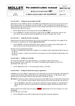
Adjustment of the sensitivity
Depending on bulk solids characteristics the sensitivity of the MWF has potentially to be adjusted. This
can be done by changing the so-called
amplitude threshold
.
1.
Insert in
line 16
a new value. Change the value in steps by 10 until you get a stable signal. The
lower the value for the amplitude threshold, the higher the sensitivity.
Examples for wrong adjusted sensitivity:
- In case of an instable measuring value the MWF is too sensitive and the amplitude threshold has to be
increased.
- In case of no signal in a filled-up silo the MWF is too insensitive and the amplitude threshold has to be
decreased.
Line 18 and 19
Setting of noise filter
The noise filter suppresses external disturbances, e.g. caused by large electric motors.
By activating the function „noise filter“, the function “disturbance signal suppression” (line 20) is
deactivated at the same time.
1.
Insert in
line 18
the value „1“ for activating the function „noise filter“.
Line 20 and 22
Setting of disturbance signal suppression
Installations (e.g. strut, ladder or measuring devices that cause an echo) near the probe could disturb the
measurement and deliver false signals that not correlate with the filling level. The disturbance signal
suppression serves to detect, buffer and eliminate these disturbance signals.
Attention!!!
In order to perform a disturbance signal, scan the MWF must be mounted at the final position
prior to this and no bulk material / liquids may reside in the scan area (5,500 mm from top).
1.
Insert in
line 20
the value „
01
“ for activating the disturbance signal suppression. The disturbance
signal suppression has to be activated before a disturbance signal scan and elimination can be
done.
Start the disturbance signal scan with a click on
START
in
line 22
und wait for the indication
„ok“ in the
field
status.
This can last up to one minute.
2.
Insert in
line 20
the value „
00
“ for deactivating the disturbance signal suppression.

