background image


Parameterisation manual 

Manual No.: 

MWF-PA102 

Microwave level measurement 

MWF


Index


0


Date 

08.08.18


Adaption of parameters with the MWF2-KIT


Page 7 of 9


3. 

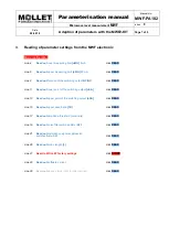
Reading of parameter settings from the MWF electronic 


Basic configuration


Line 4


Read out

 lower measuring limit 

[uMG]

 4 mA


click 

READ


Line 5


Read out

 upper measuring limit 

[oMG]

 20 mA


click 

READ


Line 9


Read out

 function of the switching output 

NC/NO


click 

READ


Line 11


Read out

 lower point of the switching output 

[uSA]


click 

READ


Line 13


Read out

 upper point of the switching output 

[oSA]


click 

READ


Line 15


Read out

 upper dead band 

[TB]


click 

READ 


Line 17


Read out

 amplitude threshold (sensitivity)


click 

READ 


Line 19


Read out

 noise filter switched 

ON

 or 

OFF


click 

READ 


Line 21


Read out

 disturbance signal suppression 

switched 

ON

 or 

OFF


click 

READ 


Line 26


Read out

 probe length 

[L]


click 

READ


Line 27


Reset to MOLLET factory settings


click 

START


Line 29


Read out

 software version


click 

READ 


Line 30


Read out

 device status (only for internal use)


click 

READ


Summary of Contents for MOLOSwave MWF2-KIT

Page 1: ...arameterisation manual Manual No MWF PA102 Microwave level measurement MWF Index 0 Date 08 08 18 Adaption of parameters with the MWF2 KIT Page 1 of 9 HART modem with mA display Parameterisation manual...

Page 2: ...2 of 9 1 Preparation Requirements MOLLET MWF2 KIT a Laptop or PC with Microsoft Windows 7 8 10 and Excel The MOLLET MWF2 KIT consists of 1 MWF HART D2 modem with mA display see first page 1 measuring...

Page 3: ...suring value display or control device 4 Connect the loosened wire with the crocodile clip of the measuring wire B 5 Put both plugs of the measuring wires A and B into the sockets A and B at the front...

Page 4: ...T D2 modem for monitoring the current output 4 20 mA This is done by pressing the red button for switching on the display After that you can read the actual measured value filling level 2 2 Parameteri...

Page 5: ...ive and the amplitude threshold has to be increased In case of no signal in a filled up silo the MWF is too insensitive and the amplitude threshold has to be decreased Line 18 and 19 Setting of noise...

Page 6: ...F will be reset to MOLLET factory settings All individual parameter settings will be overwritten with the primary MOLLET factory settings Line 28 Measuring of filling level Click on START in line 28 a...

Page 7: ...click READ Line 11 Read out lower point of the switching output uSA click READ Line 13 Read out upper point of the switching output oSA click READ Line 15 Read out upper dead band TB click READ Line...

Page 8: ...4 Signal images Examples of signal images useful for comparison with recorded signal images from you 4 1 Signal image of an empty silo Wave runs through without any significant signal up to the tensio...

Page 9: ...s There are two potential reasons for such a situation Reason 1 The signal is generated by a disturbing installation in an empty silo Action Step back to register Basic configuration and follow the in...

Reviews: