background image

Molnar Hoists 

All Rounder

 Servicing

19


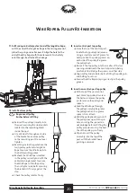
Line up pulley fork spigot 

with the hole in the end 

of the piston rod and pull 

down on the twin wire 

ropes until the fork is fully 

seated.

10


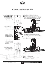
Attach double Wire Ropes to carriage:  

assemble Wire Rope ends.


Note: 

Retrieve  assembly from old Wire Ropes (springs 

and nuts etc) and attach to new Wire Rope.


Slide on spring-washer, then spring. Compress the spring 

and place a washer and fix with cable nut.  Wind nut on, 

until the screw is just proud.


Place both Wire Ropes onto carriage bracket slot and 

secure with bracket. 

   Note: 

the bracket mounts needs to be inserted between 

the spring-washer and the Wire Rope. 


Affix bracket with 

2

 x 

12

mm M6 bolts.

Wire Rope & Pulley Re-Insertion

Wire Rope & Pulley Re-Insertion

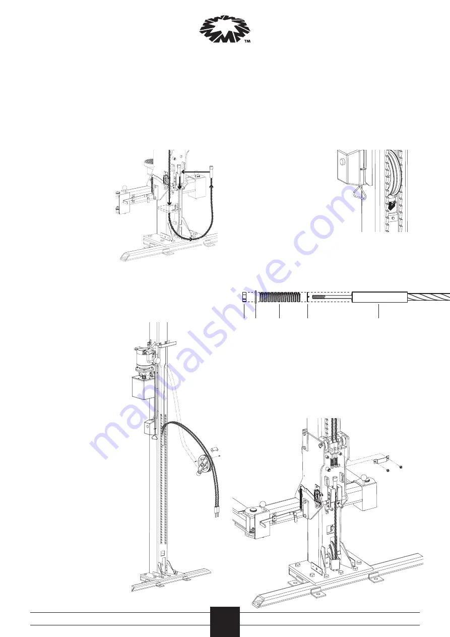
7

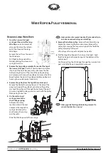
  At the bottom of the 

control-post, pull the 

end of the long Wire 

Rope down through the 

cut-out in the right-

hand side of the cable 

retaining plate.


Completely pull it out 

and sit the end into the 

back of the carriage.

8


Reinstall cylinder 

support ring:


insert into the cut-out 

sidewards, feed it over 

the top of the hydraulic 

cylinder (ensuring 

the connector plate is 

pointing downwards) 

and secure with 12mm 

M6 bolt.

9

  Reinstall double pulley: 

holding pulley in line 

with insert point; place 

Wire Ropes on pulley 

(ensuring correct and 

parallel alignment) 

and fit cable retaining 

bracket on double pulley 

(with 10mm M6 side 

bolts).


Lift pulley into larger 

cut-out in side of post, 

ensuring Wire Ropes 

sit into their grooves in 

the double pulley, when 

lowered inside the post. 


Lower down onto 

cylinder, ensuring Wire 

Ropes remain tight into 

their grooves.

cable

spring washer

spring

washer

nut

Summary of Contents for MF1705-93-OH-3T

Page 1: ...ALL ROUNDER SERVICING Maintenance for the Molnar Two Post Hoist 3Tonne MF1705 93 OH 3T OH OL 4T AS BASE ...

Page 2: ...brication 12 Hydraulic System Oil Filter Replacement 13 Electrical Controls Travel Limits 14 Structural General Check 15 Replace Pulley Bush 15 Wire Rope Pulley Removal 16 Wire Rope Pulley Re Insertion 18 Hydraulic Cylinder Replacement 22 Seal Replacement Procedure 23 Contents Key General warning Electrical hazard Servicing tip Terminology From time to time product or process descriptions can chan...

Page 3: ...ocks It is the Hoist Owner s responsibility and Duty of Care to maintain the hoist Thismustberecordedandretained Monthly ó ó Isolation points ó ó Flooring ó ó Anchor bolts ó ó Structural alignment ó ó Structural integrity ó ó Visual appearance ó ó Displayed notices ó ó Compliant clearance ó ó Safety mechanism ó ó Pick up pads ó ó Limit switches ó ó Wire ropes ó ó Check accessories ó ó Lubrication ...

Page 4: ...vy duty liquid lanolin 85 90 gear oil ó ó Hydraulic oil 5 litres AWH46 Pre Servicing Equipment Tools ó ó 2 4 metre platform style step ladder or an appropriate elevated work platform ó ó HiLift Wallaby Jack ó ó Safety prop approximately 1800mm long ó ó 1200mm spirit level ó ó Pry bar heavy and light duty ó ó Oil funnel with an end to fit into aW bsp hole ó ó Standard tool kit 2 screwdrivers Philli...

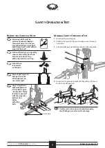
Page 5: ...hanism for damage Beforeyou Service a Hoist Servicing a Hoist must be performed and recorded by a competent person Ensure you are authorised to service a hoist and that you are familiar with all aspects of the hoist Cordon off work area using safety cones or other safety barricade Ensure area is clear of any obstruction prior to servicing Ensure there is no vehicle on the hoist Remove post covers ...

Page 6: ...nother 200mm Ensure the toggles on the back of the non control post carriage engage onto safety teeth If safety toggles do not engage toggles may need to be lubricated or springs may need to be replaced 3 Check the manual safety has automatically reset to the ON position on the control post carriage 4 Remove Jack 5 Raise the hoist and reset the safety to the OFF position and jack the control carri...

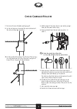
Page 7: ...reely 4 Remove side bolt and slide out roller pin roller and spacers Note the orientation of the roller as it must be refitted in the same orientation 5 Remove spacers and clean bush and pin Inspect bush and replace if necessary ensure minimal non rotational sideways movement between pin and bush The roller must be at least 60mm in diameter with no flat spots on the surface otherwise replace 6 Re ...

Page 8: ...here is excessive movement replaceWear Pads DO NOT try to shim or adjust as this may cause the carriage to jam 1 2mm Wear pad replacement 1 Remove the two M10 bolts securing the cover bracket on the side of the carriage 2 Using needle nose pliers remove the old pads and replace with new ensuring the flat face is positioned towards the post with the crosses are facing outwards 3 Refit the cover bra...

Page 9: ...eplace Pick up Pads 1 Using circlip pliers remove the circlip from the base of the pad Remove the retaining washer and unscrew pick up pad Discard 2 Remove circlip and retaining washer from new pad and screw into the lift arm Replace washer and circlip 3 Ensure that pad is secured and rotates freely Raise the Lift Rod and disengage lock mechanism to check smooth movement of arms With extension arm...

Page 10: ...along the entire length ofWire Rope Bend theWire Rope to check for frays Ropes are to be replaced according to the criteria listed below 4 Lubricate theWire Rope with approved lubricant long wire rope twin wire ropes Wire rope must be replaced if a At any point the visible number of broken wires exceeds 7 wires in 78mm length of rope or 14 wires in 390mm length of rope b The number of broken wires...

Page 11: ... post and across the top brace 7 Raise the hoist and remove the prop 8 Check the wire rope under the control unit raise hoist to maximum height and place safety prop under the non control post carriage and lower hoist back onto prop until the auto safety resets to the ON position 9 Repeat steps 2 3 4 on theWire Rope on the control post between the carriage and the bottom pulley 10 Raise hoist and ...

Page 12: ... there is not excessive free play in bush Pushpulleytoeithersideandlubricatethepin spray lubricantwithextension nozzle androtatetoworklube intobush Ensure all bolts are tight 4 Control post bottom pulley create more slack in the wire ropes use a lifting device to raise non control post up a further 200mm and lower onto safety locks Check each pulley rotates freely and there is not excessive free p...

Page 13: ...e tank to the motor reverse steps 5 to 1 Hydraulic Oil System Basic check 1 Check for oil leaks around all unions and hydraulic cylinder 2 Check level and condition of the oil in the reservoir 3 Top up as required unscrew the breather cap and use a funnel to pour Hydraulic oil to the level indicated Oil must be replaced at first service then at least every 2 years To Removethe oiltank Replacethe o...

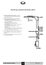
Page 14: ... disconnected at either end Side limit switch ensure it is mounted securely to its mounting point and moves freely Junction boxes check both boxes are mounted securely Control button box check the box is mounted securely to its mounting bracket Check that the cover is fitted securely and that the button moves freely 3 Check LOWERING handle pivot is operating freely Ensure it does not hold the valv...

Page 15: ...ley with steel or brass drift pin ensuring it is flush on both sides of the pulley 3 Grease the sides and affix spacers grease holds spacers in place while inserting pulley assembly into hoist 4 Re grease inside the bush pulley bush 5 Visually inspect hoist for any signs of damage rust or bent components 6 Clean posts of old lubricant and re lubricate rear tracks with spray lubricant Apply dry lub...

Page 16: ...pulley is now free of theWire Ropes place to one side Wire Rope Pulley removal Wire Rope Pulley Removal 7 Inside the control post above hydraulic cylinder is a bracket Remove one bolt and swing the bracket away PullWire Ropes down over this bracket and remove second bolt to remove 8 remove the M6 bolt holding the cylinder locating ring in position and remove ring 9 On the control post carriage rem...

Page 17: ...ou remove the pulley pin Feed the pulley out through the bottom of the post cap ensuring both pulley spacers remain with the pulley Place pulley to one side 4 On the control post carriage remove the short linkage spring between the safety mechanism and the axel Compress the long cable spring and remove the axel Remove the spring and the collar Slide theWire Rope out of the carriage axle longcables...

Page 18: ... Repeat the process for the right handWire Rope twistingWire Rope to the right to avoid twists 4 CheckWire Ropes have not crossed over 5 Ensure bothWire Ropes are positioned between cable retaining bracket lugs SecureWire Ropes with cable retaining bracket finger tighten screw one side with M6 screw swing into place and finger tighten screw on the other side Ensure the bottomWire Rope ends are sea...

Page 19: ...re Rope Pulley Re Insertion 7 At the bottom of the control post pull the end of the longWire Rope down through the cut out in the right hand side of the cable retaining plate Completely pull it out and sit the end into the back of the carriage 8 Reinstall cylinder support ring insert into the cut out sidewards feed it over the top of the hydraulic cylinder ensuring the connector plate is pointing ...

Page 20: ...op Check the pulley rotates freely 13 Insert control post top pulley From the top of the control post locate the top pulley and remove Using a small amount of grease for hold position the pulley spacers on each side of the pulley Re grease the pulley bush Reinsert the top pulley into the smaller of the two openings underneath the control post cap being careful not to dislodge the spacers on either...

Page 21: ...refit covers Readjustment of longWire Rope required after six weeks of operation 15 Attach the longWire Rope to non control post carriage Feed the threaded cable end through bracket on carriage Note the carriage may need to be raised to insert the cable end Insert spring and sleeve over cable end Insert the bracket with bracket arms positioned against the carriage and secure cable end with the cab...

Page 22: ...e and out It may need to be fed through top pulley position 8 Feed theWire Rope back into the control post so theWire Rope is secure as you lay the post down 9 Remove top brace remove the 6 x M10 bolts per side securing the brace to the post caps Remove the brace and place to one side 10 Lift control post Place asling around the post above the twin pulley ensuring the sling is above the centre of ...

Page 23: ...secured Re attach cylinder retaining ring and follow steps in reverse order to reassemble Hydraulic Cylinder Replacement retaining clip oil pipe Piston Rod Wear Ring Seal Retaining clip Seal Cylinder barrel Wear Ring Seal Clip Cylinder Piston Rod Assembly 1 Ensure the piston rod is fully compressed into the cylinder and remove the internal circlip 2 Apply compressed air to the oil pipe fitting unt...

Page 24: ... information please contact us or your local Molnar Representative 16 20 Coglin Street Brompton SA 5007 Australia T 08 7120 8700 F 08 8346 0097 E info molnarhoists com au www molnarhoists com au onwards upwards ...

Reviews: