background image

                                                      Page 5 of 22 


Rev B 

 Dec 2009 

Max

 1

8

9

0

mm


CONTENTS 


Introduction

……………………………………………………………………

6-7  

Floor Requirements…………………………………………………………….

8  

Operating Instructions………………………………………………………….

9  

Maintenance…………………………………………………………………...10 


Safety Precautio

ns……………………………………………………………11 


Replacement Parts List………………………………………………….……

12  

Parts Identification……………………………………………………….……13 


Installation Instructions……………………………………………………….

14 

Wiring Diagram………………………………………………………………..15


Electronic Diagram……………………………………………………………

16 

Hydraulic Circuit Diagram…………………………………………………….

17 

Installation Requirements…………………………………………………….18 


Certification…………………………………………………………………….

19 


SPECIFICATIONS 


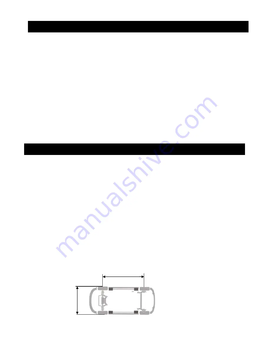
Overall width                                                                                   2093mm 
Overall length                                                                                 3664mm 
Maximum raised height                                                                  1830mm 
Minimum lowered height platform                                                    188mm 
Lifting time (working height) approx.                                                55 secs 
Lowering time (3tonnes) approx                                                      30 secs  
Electric motor  - 3 phase, 2.2kw, 2700 rpm, 415 volts, 50 hertz  
(Optional)        - Single phase, 2.2kw, 2850 rpm, 240 volts, 50 hertz  
Hoist mass       - 1080 kg   
Hydraulic oil     - Castrol Hyspin AWH46, Shell Tellus T46,  

  Mobil DTE 25, BP Bartran HV46 or equivalent  

SWL  


- 3000kg (3,0 tonnes)  

Air supply  

- Compressed air to max 7 bar, 6mm dia min supply line. 

Max Vehicle Size 


Max 3100mm 

 
                                                                                            Min 2200mm 


The Manufacturer reserves the right to alter these features and specifications without notice 


Summary of Contents for SL02

Page 1: ...Page 1 of 22 Rev B Dec 2009 MOLNAR SCISSOR LIFT HOIST SL02 INSTALLATION OPERATION MAINTENANCE MANUAL...

Page 2: ...gs given as a maximum for circuit motor protection based on DOL selection guide Voltage operating range 6 to 10 of motor nameplate Voltage Motor Voltage 240V Operation range 225V to 264V Cable sizes a...

Page 3: ...de back cover must be signed by the installer The guarantee card must be completed and returned to MOLNAR ENGINEERING PTY LTD When installed in tropical environments it is advisable to raise the hoist...

Page 4: ...Page 4 of 22 Rev B Dec 2009 Model SL02 Complies fully with the Australian Standard 1418 9 1996...

Page 5: ...4mm Maximum raised height 1830mm Minimum lowered height platform 188mm Lifting time working height approx 55 secs Lowering time 3tonnes approx 30 secs Electric motor 3 phase 2 2kw 2700 rpm 415 volts 5...

Page 6: ...ce SAFE AND EFFICIENT OPERATION Due to an electro hydraulic system which gives years of trouble free service Raising and lowering of vehicle is achieved through an electronic remote controller Sturdy...

Page 7: ...suspension springs are relaxed facilitating service and repair work Some other uses are wheel service brake adjustment spraying or sealing EASY TO OPERATE The MOLNAR SCISSOR LIFT HOIST is operated wit...

Page 8: ...of the Scissor Lift Hoist the floor must be flat and level at the anchorage points A level tolerance between bases of 8mm is allowable and 10mm front to rear Check with straight edge and spirit level...

Page 9: ...his sound is not heard immediately cease using the hoist and call an authorised service agent 6 The following steps are to be taken when lowering the hoist Press the down button twice within 2 seconds...

Page 10: ...Lubricate safety air cylinders two drops of light oil down the inlet fitting YEARLY Service and safety inspection on the hoist must be performed by a competent person This inspection must be recorded...

Page 11: ...oints while the hoist is in operation 5 Do not fail to inspect safety devices periodically to see they are in proper working condition 6 Do not make unauthorised changes to safety equipment In emergen...

Page 12: ...Cylinder 32 1 FP8211300 Spring Cylinder Check Valve 33 1 SL0203300 Spring retainer 35 1 SL0203500 Cylinder welded assembly 38 1 MF8511000 Wear ring 13691WR 43 1 SL0204300 Rod assembly 44 1 SL0204400...

Page 13: ...Page 13 of 22 Rev B Dec 2009...

Page 14: ...upply line 7 Attach the hydraulic hose from the control unit to the hoist The connection is under the Left passenger side wheel run up ramp Insure all hydraulic fittings are tight and not leaking refe...

Page 15: ...be in one hand and with the correct sized spanner in the other hand tighten the nut until the ferrule is felt to just grip the tube This point is determined by rotation or slightly rocking the tube Fr...

Page 16: ...Page 16 of 22 Rev B Dec 2009 ELECTRICAL DIAGRAM WIRING TO THIS UNIT TO COMPLY WITH AS3000...

Page 17: ...Page 17 of 22 Rev B Dec 2009 ELECTRONIC DIAGRAM...

Page 18: ...Page 18 of 22 Rev B Dec 2009 HYDRAULIC DIAGRAM...

Page 19: ...ctrical contractor to reverse motor rotation direction if incorrect 4 Check safety mechanism for loose nuts or bolts 5 Check compressed air supply pressure is at 6 to 7 bar 6 Check operation of safety...

Page 20: ...eby certify that the hoist has been checked and is in a safe operating condition and that the purchaser operator has been adequately instructed to operate the hoist Purchaser Model No SL02 Serial No D...

Page 21: ...Page 21 of 22 Rev B Dec 2009...

Page 22: ...NUFACTURED BY MOLNAR ENGINEERING PTY LTD A B N 54 007 740 794 16 20 Coglin Street Brompton S A 5007 AUSTRALIA Telephone 08 8346 6893 08 8346 6894 08 8346 8006 Fax 08 8346 0097 Email sales molnarhoists...

Reviews: