Water Systems ---
Section 6
Cayman 2005
219
To Rinse the Black Tank:
• With the solid waste drain valve left in the open posi-
tion, open the liquid (grey) waste drain valve. Gravity
will equalize the volume of the black and grey tanks.
• Close the liquid waste drain valve and turn the pump
back on to rinse the black tank. This process may be
repeated to rinse the tank again.
To Flush the Black Tank:
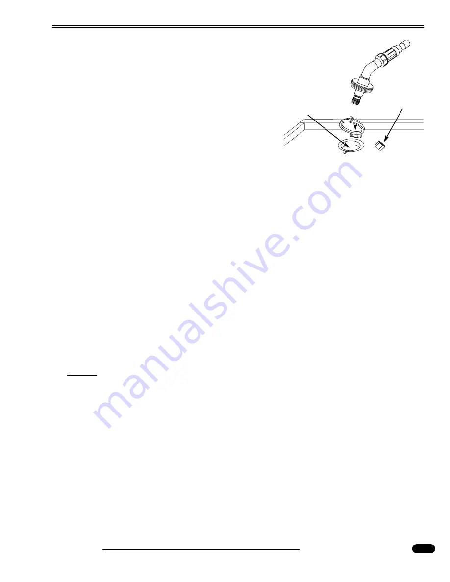
• Ensure the sewer pipe adapter is inserted in the facility
sewer connection.
• Ensure the solid waste drain valve is open, the liquid
waste drain valve is closed and the grey tank is at least 50% full.
• Connect a non-potable water hose with pressure regulator to the flush system fitting in the
plumbing service center. Turn on the water supply and waste pump. Allow the water to
rinse the black tank for at least three minutes. Never operate the system unattended.
Ensure the water flows freely through the waste pump outlet hose.
• When completed turn off the faucet.
• Close the solid waste drain valve and open the liquid waste drain valve. Turn on the waste
pump. The water in the grey tank will flush the remaining solids from the sewer hose. The
liquid waste drain valve remains open until the next drain cycle or time of departure.
When Preparing for Travel:
• Empty the tanks and close both the solid and liquid waste drain valves. Undo restraining
devices from the waste pump outlet hose. Drain the hose using a hand over hand method
while working the hose toward the shore connection. Remove sewer pipe adapter from
shore fitting and install drip cap. Coil and store hose in water bay.
• If desired, add chemical to the tanks to control odor. Follow the directions given by the
manufacturer of the chemical.
NOTE:
Drain both waste tanks before traveling.
Troubleshooting:
• The house battery disconnect switch in the battery compartment needs to be on for the
macerator pump to operate.
• 12 Volt DC power for the macerator pump is supplied by the house batteries and is protect-
ed with a 20 Amp mini breaker located in the battery bay in the electrical enclosure.
040517d
Remove Drip
Cap
Facility Sewer
Connection
Summary of Contents for Cayman 2005
Page 14: ......
Page 16: ......
Page 28: ......
Page 30: ......
Page 76: ...Section 2 Driving Safety Cayman 2005 76 100179D Weight Label...
Page 81: ...Driving Safety Section 2 Cayman 2005 81 020254 Cargo Carrying Capacity Flowchart...
Page 83: ...Driving Safety Section 2 Cayman 2005 83 020255k Actual Worksheet...
Page 84: ...Section 2 Driving Safety Cayman 2005 84 Weight Record Sheet...
Page 85: ...Driving Safety Section 2 Cayman 2005 85...
Page 86: ...Section 2 Driving Safety Cayman 2005 86 010725 010726c VIEWS Front Rear...
Page 87: ...Driving Safety Section 2 Cayman 2005 87 010723f 010724e Roadside Curbside...
Page 95: ...Driving Safety Section 2 Cayman 2005 95 NOTES...
Page 96: ...Section 2 Driving Safety Cayman 2005 96 NOTES...
Page 98: ......
Page 108: ...Section 3 Exterior Interior Care Cayman 2005 108 Fabric Specifications Charts...
Page 109: ...Exterior Interior Care Section 3 Cayman 2005 109...
Page 134: ...Section 3 Exterior Interior Care Cayman 2005 134 NOTES...
Page 136: ......
Page 165: ...Appliances Section 4 Cayman 2005 165 NOTES...
Page 166: ...Section 4 Appliances Cayman 2005 166 NOTES...
Page 168: ......
Page 203: ...Equipment Section 5 Cayman 2005 203 NOTES...
Page 204: ...Section 5 Equipment Cayman 2005 204 NOTES...
Page 206: ......
Page 229: ...Water Systems Section 6 Cayman 2005 229 WATER SYSTEM DIAGRAM 040487c Typical Layout...
Page 230: ...Section 6 Water Systems Cayman 2005 230 NOTES...
Page 232: ......
Page 250: ...Section 7 LP Gas Systems Cayman 2005 250 NOTES...
Page 252: ......
Page 286: ...Section 8 Electrical Systems House Cayman 2005 286 NOTES...
Page 288: ......
Page 292: ...Section 9 Electrical Systems Chassis Cayman 2005 292 080427f 080387C 080388c...
Page 315: ...Electrical Systems Chassis Section 9 Cayman 2005 315 ENGINE NO START FLOW CHART...
Page 316: ...Section 9 Electrical Systems Chassis Cayman 2005 316 NOTES...
Page 318: ......
Page 376: ...Section 10 Chassis Information Cayman 2005 376 LUBRICATION CHARTS 070166G FRONT...
Page 382: ...Section 10 Chassis Information Cayman 2005 382 METRIC U S CONVERSION CHART...
Page 384: ...Section 10 Chassis Information Cayman 2005 384...
Page 385: ...Chassis Information Section 10 Cayman 2005 385...
Page 386: ...Section 10 Chassis Information Cayman 2005 386...
Page 387: ...Chassis Information Section 10 Cayman 2005 387...
Page 389: ...Cayman 2005 INdex...
Page 390: ......


