➄
Sub-D-Buchse (Ansicht der Buchsenseite)
4.2.1 Alarmeingänge
Als Alarmsensoren können z. B. Bewegungssen-
soren oder Lichtschranken eingesetzt werden, die
mit einem 5-V-TTL-Ausgang, Schließer (NO = nor-
mally open) oder Öffner (NC = normally closed) aus-
gestattet sind. Die Sensoren jeweils an Masse (Kon-
takt 9) und an die folgenden Kontakte anschließen:
Sensor für Kanal 1 an Kontakt 3
Sensor für Kanal 2 an Kontakt 4
Sensor für Kanal 3 an Kontakt 5
Sensor für Kanal 4 an Kontakt 6
Die Polarität des TTL-Alarmsignals (High oder Low)
bzw. der Kontakttyp (NO oder NC) muss für jeden
Kanal separat eingestellt werden (siehe Spalte
ALARM im Menü CAMERA, Kap. 9.3). Ab Werk ist
Alarmauslösung durch einen Low-Pegel bzw.
Schließer voreingestellt.
4.2.2 Alarmausgang
Als potentialfreier Alarmausgang steht ein Relais mit
Umschaltkontakt zur Verfügung. Das Relais erlaubt
das Schalten von ohmschen Lasten bei maximal
12 V
/500 mA. An den Alarmausgang kann z. B. ein
akustischer oder optischer Alarmgeber angeschlos-
sen werden.
Im Normalzustand ist der NC-Kontakt (Pin 7) ge-
gen den gemeinsamen Kontakt COM (Pin 15) ge-
schlossen und der NO-Kontakt (Pin 8) offen. Im
Alarmfall ist der NC-Kontakt offen und der NO-Kon-
takt schließt gegen den gemeinsamen Kontakt COM.
4.2.3 Eingang zur Alarmzurücksetzung
Im Normalzustand liegt der Eingang zur Alarmzu-
rücksetzung (Pin 13) auf High-Pegel, ein Low-Pegel-
Signal [0-V-TTL-Signal oder Schließkontakt (NO)]
bewirkt das Zurücksetzen eines Alarms, noch bevor
die im Menü ALARM eingestellte Alarmdauer verstri-
chen ist.
4.2.4 Steuerausgang „Festplatte voll“
Im Normalzustand gibt der Ausgang (Pin 12) ein
High-Pegel-Signal (5 V) aus. Ist die Speicherkapa-
zität der Festplatte erschöpft, wechselt das Signal
auf Low-Pegel (0 V) und kann damit die Aufnahme
eines hier angeschlossenen zweiten Digitalrecor-
ders starten.
4.2.5 Fernsteuerung
Über die RS-232- oder die RS-485-Schnittstelle
lässt sich das Gerät über einen Computer oder ein
Terminal fernsteuern. Für eine komfortable Fern-
steuerung über ein LAN ist der Einsatz des Video-
Servers VWS-200 von MONACOR zu empfehlen.
Bei Fernsteuerung des Geräts ist dieses nur
Datenempfänger, kann also keine Daten, wie Rück-
meldungen, senden. Die Codierung der einzelnen
Funktionen ist in Kapitel 11 angegeben.
Verwendung der RS-232-Schnittstelle:
Pin 2 (RX) und Pin 9 (Masse) mit den entspre-
chenden Kontakten am Steuergerät verbinden.
Verwendung der RS-485-Schnittstelle:
Pin 11 (A) und Pin 10 (B) mit den entsprechenden
Kontakten am Steuergerät verbinden. Die Ab-
schirmung mit Pin 9 (Masse) verbinden.
Tipp: Die Verwendung verdrillter Leitungen verrin-
gert Störeinstrahlungen.
5 Inbetriebnahme
1) Nach dem Anschluss aller Geräte das beiliegen-
de Netzgerät mit der Buchse DC 19V (21) verbin-
den und über das mitgelieferte Netzkabel an eine
Steckdose (100 – 240 V~/50 – 60 Hz) anschlie-
ßen. Die Initialisierung des Geräts startet:
Die Betriebsanzeige (16) leuchtet orangefar-
ben und alle LEDs (8) außer der LED HDD leuch-
ten kurz auf. Auf dem Bildschirm des Hauptmoni-
tors werden kurz die Videonorm (PAL bzw. NTSC)
und die Software-Version eingeblendet. Bei kor-
rekt installierter Festplatte erscheint danach die
Meldung „HDD DETECTING“, gefolgt von „MAS-
TER HDD CONNECTED“.
(Erscheint stattdessen „HDD NOT FOUND“, ist
die Festplatte nicht richtig installiert oder keine
Festplatte installiert. Auch ohne installierte Fest-
platte lässt sich das Gerät zur Live-Überwachung
als Quad-Prozessor nutzen.)
2) Nach der Initialisierung ist der Recorder betriebs-
bereit: Die Betriebsanzeige leuchtet grün.
Bei der ersten Inbetriebnahme sind die ab Werk
vorprogrammierten Grundeinstellungen aktiv:
In der LED-Reihe (8) leuchten
die Anzeige TIMER (d. h. die Timer-Funktion ist
eingeschaltet, siehe Kap. 9.2) und die Anzeige
ALARM (d. h. die Funktion „externer Alarm“ ist
eingeschaltet, siehe Kap. 9.5).
Auf dem Bildschirm des Hauptmonitors
sind für die 4 Kamerakanäle die Bezeichnun-
gen „CAMERA01“ bis „CAMERA04“ und eine
Datums- und Uhrzeitangabe eingeblendet.
3) Um die Grundeinstellungen zu ändern und das
Gerät auf die Bedürfnisse der jeweiligen Anwen-
dung zu programmieren, siehe Kap. 9.
4) Zum Ausschalten den Netzstecker des Netz-
geräts aus der Steckdose ziehen.
Das Gerät nicht in einem kurzen Zeitraum in und
außer Betrieb nehmen: Zwischen der Inbetriebnah-
me und dem Trennen vom Stromnetz müssen min-
destens 3 s liegen.
1
9
8
15
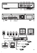
4.1 Video connections
1) Connect the video outputs of the cameras to the
BNC jacks VIDEO IN 1 – 4 (18).
2) Connect the video input of the main monitor for
live surveillance in various display formats to the
jack VIDEO OUT MAIN (19). This monitor also
displays the recordings and the pages of the on-
screen menu.
3) For display of all camera pictures in the full
screen format with automatic sequential switch-
ing of pictures, a second monitor can be connect-
ed to the jack VIDEO OUT CALL (20). Channels
which are not used will be skipped during the
automatic sequential switching. The dwell time
can be separately adjusted for each channel in
the menu DWELL (chapter 9.6).
4.2 Alarm and control connections
Via the 15-pole Sub-D jack EXTERNAL I/O (17), the
unit provides various inputs and outputs for control
and alarm evaluation. For connection, a matching
15-pole plug is supplied with the recorder.
➄
Sub-D jack (view of the jack side)
4.2.1 Alarm inputs
As alarm sensors e. g. motion detectors or light bar-
riers can be used which are equipped with a 5 V TTL
output, an NO (normally open) contact, or an NC
(normally closed) contact. Connect the sensors re-
spectively to ground (contact 9) and to the following
contacts:
sensor for channel 1 to contact 3
sensor for channel 2 to contact 4
sensor for channel 3 to contact 5
sensor for channel 4 to contact 6
The polarity of the TTL alarm signal (high or low) or
the contact type (NO or NC) must be set separately
for each channel (see column ALARM in the menu
CAMERA, chapter 9.3). The alarm triggering is fac-
tory-set by a low level or NO contact.
4.2.2 Alarm output
A relay with change-over contact is available as a
floating alarm output. The relay allows switching of
ohmic loads at max. 12 V
/500 mA. At the alarm
output, e. g. an acoustic or optical alarm device can
be connected.
In normal mode, the NC contact (pin 7) is closed
against the common contact COM (pin 15) and the
NO contact (pin 8) is open. In case of alarm, the NC
contact is open and the NO contact is closed against
the common contact COM.
4.2.3 Input for alarm reset
In normal mode, the input for alarm reset (pin 13) is
at high level; a low level signal (0 V TTL signal or NO
contact) will cause reset of an alarm even before the
alarm time adjusted in the menu ALARM is expired.
4.2.4 Control output “Disk Full”
In normal mode, the output (pin 12) sends a high
level signal (5 V). If the storage capacity of the hard
disk is exhausted, the signal changes to low level
(0 V) and is thus able to start the recording of a
second digital recorder connected to this output.
4.2.5 Remote control
Via the RS-232 or the RS-485 interface, the unit can
be remote-controlled via a computer or terminal.
For a convenient remote control via LAN, it is re-
commended to use the MONACOR video server
VWS-200.
In case of remote control of the unit, it is merely
able to receive data; it is not able to send any data
e. g. reply messages. The coding of the individual
functions can be found in chapter 11.
Use of the RS-232 interface:
Connect pin 2 (RX) and pin 9 (ground) to the cor-
responding contacts on the control unit.
Use of the RS-485 interface:
Connect pin 11 (A) and pin 10 (B) to the corre-
sponding contacts on the control unit. Connect
the screening to pin 9 (ground).
Note: Interference will be reduced if twisted wires
are used.
5 Setting the Unit into Operation
1) After connection of all units, connect the supplied
power supply unit to the jack DC 19V (21) and
via the supplied mains cable to a socket
(100 – 240 V~/50 – 60 Hz). The inititalization of
the units starts:
The power LED (16) shows orange and all
LEDs (8) light up, except the LED HDD. The
screen of the main monitor shortly displays the
video standard (PAL or NTSC) and the software
version. With the hard disk correctly installed, the
message “HDD DETECTING” is inserted, fol-
lowed by “MASTER HDD CONNECTED”.
(If “HDD NOT FOUND” is inserted, instead the
hard disk is not correctly installed or no hard disk
is installed. Even without a hard disk installed,
the unit can be used as a quad processor for live
surveillance.)
2) After the initialization, the recorder is ready for
operation: The power LED shows green.
When setting the unit into operation for the first
time, the factory settings are active:
In the LED row (8)
the LED TIMER (i.e. the timer function is
activated, see chap. 9.2) and the LED ALARM
(i.e. the function “external alarm” is activated,
see chapter 9.5) light up.
On the screen of the main monitor
the designations “CAMERA01” to “CAMERA04”
for the 4 camera channels and a date and time
indication are inserted.
Do not switch on and off the unit within a short inter-
val. There must be at least 3 seconds between
switching on and off.
1
9
8
15
7
GB
D
A
CH


