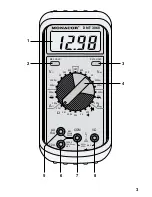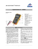
1) Connect the red test lead to jack “V
Ω
” (8) and the black test
lead to jack “COM” (7).
2) For AC voltage measurements set the rotary switch (4) to one of
the “V~” ranges, for DC voltage measurements to one of the
“V
” ranges. Preferably start with the 600 V range.
3) Hold the test tips to the measuring object and read the measur-
ing value on the display (1). In case of DC voltage measure-
ments, a minus sign will precede the measuring value if the
negative pole is at the red test tip and the positive pole at the
black test tip.
5.2 Current measurement
●
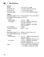
The DC current max. to be measured must not exceed 10 A.
●
If the multimeter is set to current measurement [red test lead
connected to jack “µA mA”(5) resp. “10 A” (6)], do not feed volt-
age to the meter! Both multimeter and voltage source may be
damaged in this case.
1) For current measurements below 200 mA, connect the red test
lead to the jack “µA mA” (5) and the black test lead to the jack
“COM” (7).
For current measurements from 200 mA on, connect the red
test lead to jack “10 A” (6) and the black test lead to the jack
“COM” (7).
2) For AC current measurements set the rotary switch (4) to one of
the “A~” ranges, for DC current measurements to one of the
“A
” ranges. Preferably start with the maximum range.
3) Separate the circuit to be measured from the power supply.
Open up the circuit and connect the multimeter in series to the
circuit.
4) Read the measuring value on the display (1). In case of DC cur-
rent measurements, a minus sign will precede the measuring
value if the negative pole is at the red test tip and the positive
pole at the black test tip.
5.3 Resistance measurement and continuity test
●
The unit is overload-protected up to 500 V~/
. In spite of this
protection do not measure within a circuit if it carries voltage!
GB
15


