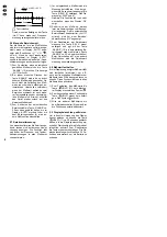
Please unfold page 3. Then you can
always see the operating elements
and connections described.
Contents
1
Operating Elements and
Connections . . . . . . . . . . . . . 13
2
Safety Notes . . . . . . . . . . . . . 14
3
Applications . . . . . . . . . . . . . 14
4
Setting into Operation . . . . . 14
5
Carrying out Measurements 14
5.1
Voltage measurement . . . . . . . 14
5.1.1 Measurements in the 25 mV
range . . . . . . . . . . . . . . . . . . . . 15
5.2
Current measurement . . . . . . . 15
5.3
Resistance measurement,
continuity and diode tests . . . . 15
5.4
Capacitance measurement . . . 16
5.5
Frequency and pulse duty
factor measurements . . . . . . . 16
5.6
Manual range selection . . . . . . 17
5.7
Relative value measurement . 17
5.8
“Freezing” a measured value . 17
5.9
Activating
the display illumination . . . . . . 17
6
Replacing the Battery or
the Fuses . . . . . . . . . . . . . . . . 18
7
Operation via a Computer . . 18
7.1
Installing the DMM40 software 18
7.2
Setting up a connection to the
computer . . . . . . . . . . . . . . . . . 19
7.3
Acquisition of the measured
values with the computer . . . . 19
7.3.1 Functions in the main menu . . 19
7.3.2 Graphic representation . . . . . . 20
7.3.3 Recording
the measured values . . . . . . . . 20
8
Specifications . . . . . . . . . . . . 21
1
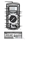
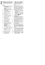
Operating Elements and
Connections
1 Connection for a computer with
RS-232 interface
2 Display
3 Button “REL
∆
” for switching on and
off the relative value measurement
4 Button “RS232” for activating and
deactivating the data transfer to a
connected computer
5 Yellow button for switching
1. from DC to AC current measure-
ment if the range switch (6) is in a
current range
2. from resistance measurement to
continuity or diode tests if the
range switch is in the position “
Ω
/
”
6 Range switch
7 Jack “COM” for the black test lead
(negative pole)
8 Jack “25mV/µA/mA” for the red test
lead (positive pole) for current
measurement up to 250 mA and for
voltage measurement up to 25 mV
9 Jack “A” for the red test lead (positive
pole) for current measurement from
250 mA to 10 A
10 Button “RANGE” for manual range
selection
11 Button “HOLD” for “freezing” a
measured value and for switching on
the display illumination (keep the but-
ton pressed for approx. 2 seconds)
12 Button “Hz-%” for switching from fre-
quency measurement to pulse duty
factor measurement of a signal in
percent if the range switch is in the
position “Hz”
13 Red jack for the red test lead (posi-
tive pole) for measurements of volt-
age, resistance, capacitance, and
frequency
GB
13


