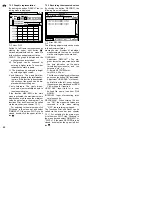
(8 or 9), except for measurements in
the 25 mV range. Otherwise the
meter and the voltage source may be
damaged.
2) For AC voltages, set the range switch
(6) to the position “~V”, for DC volt-
ages to the position “
V”, or for
measurements up to 250 mV to the
position “
mV”.
3) Hold the test tips to the object to be
measured or to the measuring points
and read the measured value on the
display (2).
4) In case of DC voltage measure-
ments, a minus sign will precede the
measured value if the negative pole
is at the red test tip and the positive
pole is at the black test tip. If the
250 mV range is exceeded, “OL” is
displayed. In this case, switch to the
higher range “
V”.
5.1.1 Measurements in the 25 mV
range
For precise measurement of very low DC
and AC voltages, a 25 mV range each is
available. Do not use these ranges until
a voltage of up to 25 mV has been found
in the range “
mV” or “~V” (chapter 5.1).
1) Connect the red test lead to the yel-
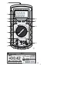
low jack “25mV/mA/mA” (8) and the
black test lead to the black jack
“COM” (7).
2) For AC voltages, set the range switch
(6) to the position “25mV~”, for AC
voltages to the position “25mV
”.
3) If the 25 mV range is exceeded, “OL”
is displayed. In this case, disconnect
the red test lead from the yellow jack,
switch to the range “
mV” or “~V”
and connect the red test lead to the
red jack “V
Ω
/Hz” (13).
5.2 Current measurement
●
The maximum current to be meas-
ured must not exceed 10 A.
●
Except for measurements in the
25 mV range, never accidentally feed
voltage to the meter while the red test
lead is connected to one of the two
yellow jacks for the current measure-
ment (8 or 9). Otherwise the meter and
the voltage source may be damaged.
1) Connect the red test lead to the yel-
low jack “A” (9) and the black test
lead to the black jack “COM” (7).
2) Set the range switch (6) to the posi-
tion “A” and for AC voltages, addition-
ally switch to AC voltage measure-
ment with the yellow button (5). In-
stead of “DC”, “AC” will be displayed.
3) Open the circuit to be measured and
connect it to the meter. Currents of
10 A must only be measured for a
short time (max. 60 seconds), other-
wise the internal heating will result in
inaccurate measurements. Wait for
approx. 10 minutes before continuing
with the next 10 A measurement.
4) If the negative pole is at the red test
tip and the positive pole is at the
black test tip in case of a DC current,
a minus sign will precede the
measured value in the display.
5) To obtain a more accurate measure-
ment if the measured current is less
than 250 mA, connect the red test lead
to the yellow jack “25mV/µA/mA” (8)
and set the range switch to the posi-
tion “mA”. Press the yellow button to
return to AC current measurement, if
required.
In case of a measured value of
less than 2.5 mA, switch to the µA
range. “OL” is displayed if the range
is exceeded.
6) If no current measurement is pos-
sible, check the fuses and replace
them, if required – see chapter 6 “Re-
placing the Battery or the Fuses”.
5.3 Resistance measurement,
continuity and diode tests
●
The meter is overload-protected up
to 500 V
/~. Nevertheless, do not
measure within a circuit if it carries
voltage!
●
Aways measure a resistor or a diode
separately, otherwise the measure-
ment will be inaccurate. For this pur-
pose, the object to be measured must
be soldered out of the circuit, if re-
quired.
1) Connect the red test lead to the red
jack “V
Ω
/Hz” (13) and the black
test lead to the black jack “COM” (7).
GB
15


