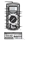
2) Set the range switch (6) to the posi-
tion “
Ω
/
”.
3) For resistance measurements, “M
Ω
”
must be displayed. “OL” is displayed
as long as nothing is measured.
For diode tests, press the yellow but-
ton (5) once. The diode symbol
is
displayed.
For continuity tests, press the yellow
button for a second time. The buzzer
symbol is
displayed.
A third actuation of the yellow button
will switch back to resistance measure-
ment.
4) Hold the test tips to the object to be
measured or to the corresponding
measuring points and read the
measured value on the display.
If “OL” is displayed during resistance
measurements, the resistor is inter-
rupted or its value exceeds 25 M
Ω
.
The buzzer will sound during conti-
nuity tests if the contact resistance
is less than 30
Ω
.
For diode tests, hold the cathode of
the diode to the black test tip and the
anode to the red test tip. The forward
voltage up to 0.999 V at a test current
of approx. 0.5 mA is displayed. In
case of silicon diodes, the value is
approx. 0.7 V.
With a display of approx. 0 V, the
diode has a short circuit. If “OL” is dis-
played, the diode is interrupted,
connected in reverse direction
(change the polarity of the diode), or
the forward voltage exceeds 0.999 V.
5.4 Capacitance measurement
1) Connect the red test lead to the red
jack “V
Ω
/Hz” (13) and the black
test lead to the black jack “COM” (7).
2) Set the range switch (6) to the posi-
tion “
”.
3) Press the button “REL
∆
” (3) to com-
pensate any disturbing capacitance.
“
∆
” is displayed.
4) Discharge the capacitor and hold it
to the test tips.
5) Read the measured value on the dis-
play. It may take several seconds un-
til the correct value is displayed. If
“OL” is displayed, the capacitance
exceeds 25 µF or the capacitor has a
short circuit.
5.5 Frequency and pulse duty fac-
tor measurements
●
The maximum voltage to be meas-
ured must not exceed 500 V~. Other-
wise there will be danger of life!
1) Connect the red test lead to the red
jack “V
Ω
/Hz” (13) and the black
test lead to the black jack “COM” (7).
2) Set the range switch (6) to the posi-
tion “Hz”. “Hz” is displayed.
3) Hold the test tips to the correspond-
ing measuring points and read the
frequency on the display. The ampli-
tude of the voltage to be measured
must be min. 1 V for frequencies up to
500 kHz and min. 5 V for frequencies
up to 5 MHz, otherwise there will be
no (correct) display.
4) For frequencies between 2 Hz and
20 kHz the pulse duty factor can be
displayed in %. For this purpose,
shortly press the button “Hz-%” (12).
“%” instead of “Hz” is displayed. The
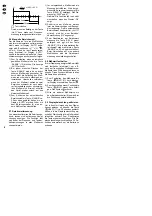
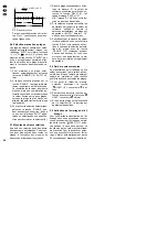
pulse duty factor indicates the ratio of
the duration of the positive signal
share to the period, e. g.:
➂
Pulse duty factor
A repeated actuation of the button
“Hz-%” will switch back to frequency
measurement.
10 ms
6,5 ms
0
U
t
6,5 ms
x 100 % = 65 %
10 ms
GB
16

