Ecklautsprecher
Bitte lesen Sie diese Anleitung vor der Installation gründ-
lich durch und heben Sie sie für ein späteres Nachlesen
auf.
1 Verwendungsmöglichkeiten
Dieses kompakte Lautsprecherpaar dient zur Be schallung
mit Sprache und Hintergrundmusik. Das Gehäuse in Form
einer
1
⁄
8
-Kugel ist ideal für die Montage in einer Raumecke
oder für die Kombination mehrerer Lautsprecher an der
Wand oder Decke (
Abb. 6).
2 Wichtige Hinweise für den Gebrauch
Die Lautsprecher entsprechen allen erforderlichen Richtli-
nien der EU und sind deshalb mit
gekennzeichnet.
G
Die Lautsprecher sind nur zur Verwendung im Innenbe-
reich geeignet. Schützen Sie sie vor Tropf- und Spritz-
wasser, hoher Luftfeuchtigkeit und Hitze (zu
lässiger
Einsatztemperaturbereich 0 – 40 °C).
G
Verwenden Sie zum Reinigen nur ein trockenes, wei-
ches Tuch, niemals Wasser oder Chemikalien.
G
Werden die Lautsprecher zweckentfremdet, nicht fach-
gerecht montiert, falsch angeschlossen oder überlastet,
kann keine Haftung für daraus resultierende Sach- oder
Personenschäden und keine Garantie für die Lautspre-
cher übernommen werden.
Sollen die Lautsprecher endgültig aus dem
Betrieb genommen werden, übergeben Sie sie
zur umweltgerechten Entsorgung einem örtli-
chen Recyclingbetrieb.
3 Installation
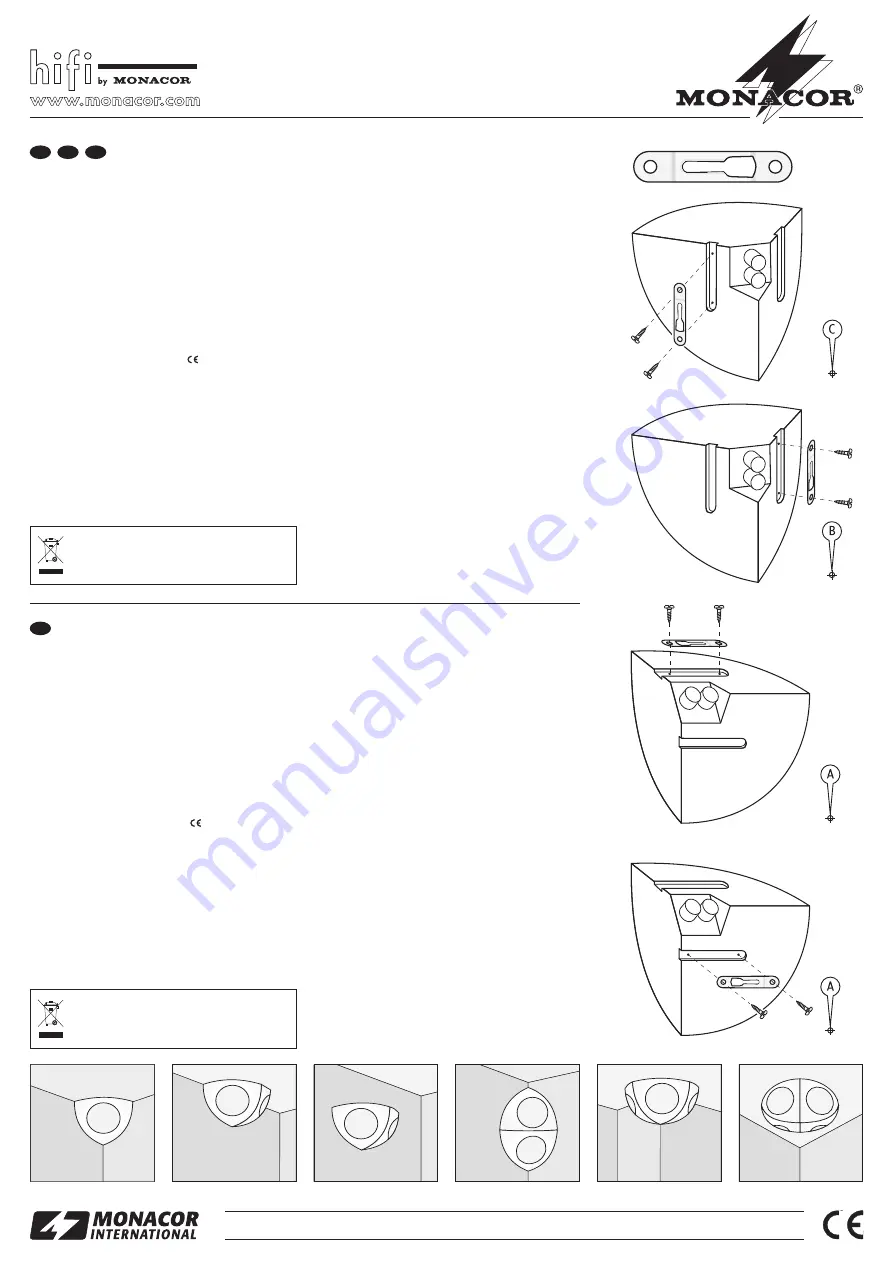
1) Jeder Lautsprecher wird mit einer Halterung (Abb. 1)
befestigt. Je nach Ausrichtung des Lautsprechers
(
Abb. 2 – 5) die Halterung mit zwei kurzen Schrau-
ben am Lautsprecher befestigen.
2) Stellen Sie sicher, dass an der Montagestelle in der
Wand oder Decke keine Leitungen verlaufen, die durch
das Bohren beschädigt werden können.
3) Die beiliegende Bohrschablone am Montageort platzie-
ren und das in der entsprechenden Abbildung angege-
bene Bohrloch (A/ B/C) anzeichnen. Das Loch bohren
und mit dem passenden Dübel die lange Schraube so
hineindrehen, dass der Kopf etwa 4 – 6 mm heraussteht.
4) Die Lautsprecherkabel an die Klemmen anschließen
(Rot = +, Schwarz = -). Beim Zusammenschalten meh-
rerer Lautsprecher darauf achten, dass die minimal
zulässige Lastimpedanz des Verstärkers nicht unter-
schritten wird.
5) Den Lautsprecher mit der Halterung auf den Schrau-
benkopf setzen und in die Zielposition schieben. Lässt
sich der Lautsprecher nicht ganz in seine Zielposition
schieben oder sitzt er zu locker, die Schraube etwas
weiter heraus- bzw. hineindrehen.
4 Technische Daten
Belastbarkeit/ Impedanz: . . . . . . . . . . . . . 15 W
RMS
, 30 W
MAX
/ 8 Ω
Frequenzbereich: . . . . . . . . . . . . . . . . . . 100 – 20 000 Hz
Mittlerer Schalldruck (1 W / 1 m): . . . . . . . 87 dB
Abmessungen/ Gewicht (Paar): . . . . . . . . Radius = 140 mm / 1,5 kg
Änderungen vorbehalten.
MKS-48/ WS
Best.-Nr. 13.2130
Corner Speakers
Please read these operating instructions carefully prior to
the installation and keep them for later reference.
1 Applications
This compact pair of speakers serves for PA applications
with speech and background music. The cabinet in the
form of a
1
⁄
8
sphere is ideal for being mounted into the
corner of a room or for combining several speakers on the
wall or ceiling (
fig. 6).
2 Important Notes
The speakers correspond to all required directives of the
EU and are therefore marked with
.
G
The speakers are only suitable for indoor applications.
Protect them against dripping water and splash water,
high air humidity, and heat (admissible ambient temper-
ature range 0 – 40 °C).
G
For cleaning only use a dry, soft cloth, never use water
or chemicals.
G
No guarantee claims for the speakers and no liability for
any resulting personal damage or material damage will
be accepted if the speakers are used for other purposes
than originally intended, if they are not mounted in an
expert way, not correctly connected, or overloaded.
If the speakers are to be put out of operation
definitively, take them to a local recycling plant
for a disposal which is not harmful to the envi-
ronment.
3 Installation
1) Each speaker is fixed with one bracket (fig. 1). Depend-
ing on the alignment of the speaker (
figs. 2 to 5) fix
the bracket with two short screws at the speaker.
2) Make sure that no cables run in the wall or ceiling at the
mounting place which may be damaged by drilling.
3) Place the supplied drilling template at the mounting
place and mark the drill hole (A/ B/C) indicated in the
corresponding figure. Drill the hole and turn the long
screw with the matching dowel into the hole so that the
head protrudes approx. 4 to 6 mm.
4) Connect the speaker cables to the terminals (red = +,
black = -). When interconnecting several speakers,
make sure that their total impedance does not fall
below the minimum admissible load impedance of the
amplifier.
5) Place the speaker with the bracket on the screw head
and slide it into the target position. If it is not possible to
slide the speaker completely into its target position or if
it is too loose, slightly turn the screw further in or out.
4 Specifications
Power rating/impedance: . . . . . . . . . . . . 15 W
RMS
, 30 W
MAX
/ 8
Ω
Frequency range: . . . . . . . . . . . . . . . . . . 100 – 20 000 Hz
SPL (1 W / 1 m): . . . . . . . . . . . . . . . . . . . . 87 dB
Dimensions/weight (pair): . . . . . . . . . . . . radius = 140 mm / 1.5 kg
Subject to technical modification.
®
MONACOR INTERNATIONAL GmbH & Co. KG • Zum Falsch 36 • 28307 Bremen • Germany
Copyright
©
by MONACOR INTERNATIONAL. All rights reserved.
A-0902.99.02.08.2011
®
D
A
CH
GB


