6
English
Deutsch
Deutsch Seite
Français
Français Page
Italiano
Italiano Pagina
Español
Español Página
Nederlands
Nederlands Pagina
Polski
Polski Strona
PA-912S
PROT
CLIP
SIG
PWR
100V
70V
LEVEL
230 V~/50 Hz
OUTPUT
LINK
INPUT
COM COM COM
70V/
100V
100V
LIFT
GND
70V
1
1
2
2
3
3
1
2
3
4
5
6
7
7
8
9
10
PA Power Amplifier
These instructions are intended for installers
with specific knowledge in sound reproduc-
tion using 100 V technology . Please read the
instructions carefully prior to installation and
keep them for later reference .
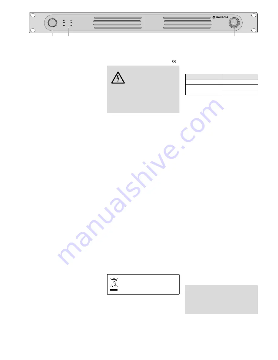
1 Overview
1
Volume control LEVEL
2
LED indicators
PROT
will briefly light up after switching on
(switch-on delay) or to indicate over-
heating or a fault in the amplifier
CLIP
will light up to indicate overload [turn
back the volume control LEVEL (1)]
SIG
will light up at a specific signal level
(depending on the control LEVEL)
PWR
power LED
100 V
operating mode for 100 V speakers
70 V
operating mode for 70 V speakers
3
On / off switch
4
Mains jack for connection to a mains
socket (230 V/ 50 Hz) via the mains cable
provided
5
Speaker terminals OUTPUT
Important!
Always place the protective
cover over the terminals when operating
the amplifier!
6
Selector switch for operation with 100 V
speakers or 70 V speakers
7
Fans (model PA-912S with one fan only)
8
Ground lift switch
LIFT = signal ground and amplifier hous-
ing are separated
GND = signal ground and amplifier hous-
ing are electrically connected
9
Feed-through output LINK to connect, for
example, another PA amplifier
The input signal of the jack INPUT (10) is
available at this output .
10
LINIE signal input (combined XLR
/
6 .3 mm jack, bal .) for connection to a
signal source
2 Safety Notes
This unit corresponds to all relevant directives
of the EU and is therefore marked with .
WARNING
The unit uses dangerous
mains voltage . Leave servicing
to skilled personnel only and
never insert anything into the
air vents: Risk of electric shock!
During operation, there is a hazard of con-
tact with a dangerous voltage of up to 100 V
at the right screw terminal OUTPUT (5) .
Always place the protective cover when
operating the amplifier!
•
The unit is suitable for indoor use only . Pro-
tect it against dripping water, splash water
and high air humidity . The admissible ambi-
ent temperature range is 0 – 40 °C .
•
Do not place any vessel filled with liquid on
the unit, e . g . a drinking glass .
•
The heat produced inside the unit must be
dissipated by air circulation . Never cover
the air vents of the housing .
•
Do not operate the unit and immediately
disconnect the mains plug from the socket
1 . if the unit or the mains cable is visibly
damaged,
2 . if a defect might have occurred after the
unit was dropped or suffered a similar
accident,
3 . if malfunctions occur .
In any case, the unit must be repaired by
skilled personnel .
•
Never pull the mains cable to disconnect
the mains plug from the socket, always
seize the plug .
•
For cleaning only use a dry, soft cloth; never
use water or chemicals .
•
No guarantee claims for the unit and no li-
ability for any resulting personal damage or
material damage will be accepted if the unit
is used for other purposes than originally
intended, if it is not correctly connected
or operated, or if it is not repaired in an
expert way .
If the unit is to be put out of oper-
ation definitively, take it to a local
recycling plant for a disposal which
is not harmful to the environment .
3 Applications
The amplifier series PA-9 . .S is specially de-
signed for PA systems and suited both for
100 V systems and 70 V systems . The output
power is:
Model
Power rating
PA-912S
120 W
PA-924S
240 W
PA-948S
480 W
4 Setting up and
Connecting the Amplifier
The amplifier is designed for installation into a
rack (482 mm /19”), but it can also be placed
on a table . To ensure sufficient cooling of the
power amplifier, air must always be able to
flow freely through all air vents .
4.1 Rack installation
For installation into a rack, 1 RS (rack space
= 44 .45 mm) is required . To prevent the rack
from becoming top-heavy, insert the amplifier
into the lower section of the rack . The front
panel alone is not sufficient for fixing the am-
plifier safely; additionally use lateral rails or a
bottom plate to secure it .
The heat produced by the amplifier must
be dissipated from the rack; otherwise, heat
will accumulate in the rack which may not
only damage the amplifier but also other
units in the rack . In case of insufficient heat
dissipation, install a ventilation module (e . g .
DPVEN-03) into the rack .
4.2 Connecting the amplifier
Always switch off the amplifier before making
or changing any connections!
4.2.1 Speakers
Connect the PA speakers to the terminal strip
OUTPUT (5) . Before connecting, remove the
transparent protective cover .
Make sure that the polarity is the same
for all speakers (e . g . COM = negative termi-
nal) . The total load of the speakers must not
exceed the power rating of the amplifier (see
chapter 3); otherwise, the protective circuit
will respond and mute the amplifier .
Important!
After connecting the speak-
ers, replace the protective cover to prevent
contact with the terminal strip . During
operation, there is a hazard of contact with
a dangerous voltage of up to 100 V at the
right screw terminal .
English
English Page
Summary of Contents for PA-912S
Page 2: ......


