ELA-Einbaulautsprecher
1 Verwendungsmöglichkeiten
Dieser ELA-Lautsprecher ist speziell für den Einsatz in
ELA-Anlagen konzipiert, die mit 100-V-Technik arbei-
ten. Durch die einteilige Kunststoffausführung, die
hochwertige Polypropylen-Membran und die Gummi-
sicke ist er unempfindlich gegen Spritzwasser und
lässt sich auch im Außenbereich einsetzen (IP-Schutz-
klasse IP 44).
2 Wichtige Hinweise für den sicheren
Gebrauch
Der Lautsprecher entspricht der Richtlinie für elektro-
magnetische Verträglichkeit 89/336/EWG und der
Niederspannungsrichtlinie 73/23/EWG.
●
Wird der Lautsprecher zweckentfremdet, nicht fach-
gerecht angeschlossen oder überlastet, kann keine
Haftung für daraus resultierende Sach- oder Perso-
nenschäden und keine Garantie für den Lautspre-
cher übernommen werden.
●
Soll der Lautsprecher endgültig aus dem Betrieb ge-
nommen werden, übergeben Sie ihn zur umwelt-
gerechten Entsorgung einem örtlichen Recycling-
betrieb.
3 Montage
1) In die Decke oder Wand ein entsprechend großes
Loch sägen (siehe technische Daten).
2) Den elektrischen Anschluss herstellen (Kapitel 4).
3) Bei der Installation im Außenbereich entsprechen-
des Dichtungsmaterial zwischen Lautsprecher und
Montagefläche einsetzen, damit keine Feuchtigkeit
ins Innere gelangt. Den Lautsprecher mit den bei-
liegenden Montageschrauben festschrauben.
4 Elektrischer Anschluss
Warnung: Im Betrieb liegt berührungsgefähr-
liche Spannung bis 100 V an den Anschluss-
klemmen an.
Die Installation darf nur durch Fachpersonal er-
folgen.
Achten Sie auf die richtige Leistungsanpas-
sung. Eine falsche Anpassung führt zur Zer-
störung des ELA-Verstärkers!
1) Falls die ELA-Anlage eingeschaltet ist, diese zuerst
komplett ausschalten!
2) Den Lautsprecher über die Anschlussklemme an-
schließen: Die schwarze Ader (Minuspol) und eine
der anderen farbigen Adern, die der gewünschten
B
Nennbelastung durch den Lautsprecher entspricht,
mit dem Ausgang des ELA-Verstärkers verbinden.
3) Beim Anschluss von mehreren Lautsprechern dar-
auf achten, dass die Lautsprecher alle gleich gepolt
werden (schwarze Ader = Minuspol) und dass der
ELA-Verstärker nicht überlastet wird.
Änderungen vorbehalten.
PA Chassis Speaker
1 Applications
This PA speaker is specially designed for application in
PA systems operating with a 100 V technique. Due to
the one-piece plastic design, the high-quality polypro-
pylene cone, and the rubber surround, the speaker is
protected against splash water and therefore also suit-
able for outdoor installation (protective class IP 44).
2 Safety Notes
The speaker corresponds to the directive for electro-
magnetic compatibility 89/336/EEC and to the low
voltage directive 73/23/EEC.
●
No guarantee claims for the speaker and no liability
for any resulting personal damage or material dam-
age will be accepted if the speaker is used for other
purposes than originally intended, if it is not correct-
ly connected or if it is overloaded.
●
If the speaker is to be put out of operation defini-
tively, take it to a local recycling plant for a disposal
which is not harmful to the environment.
3 Mounting
1) Saw a hole of the required size into the ceiling or
wall (see specifications).
2) Make the electrical connection (chapter 4).
3) For outdoor installation of the speaker, insert a suit-
able sealing material between the speaker and the
mounting surface to prevent penetration of humi-
dity. Fasten the speaker by means of the mounting
screws supplied.
4 Electrical Connection
Warning: During operation, there is a hazard of
contact with a voltage of up to 100 V at the ter-
minals.
The installation must be carried out by skilled
personnel only.
Observe the correct power matching. An incor-
rect matching will damage the PA amplifier!
1) If the PA system is switched on, switch it off com-
pletely before connecting it!
2) Connect the speaker via the terminal: Connect the
black core (negative pole) and one of the coloured
B
cores corresponding to the desired rated load by
the speaker to the output of the PA amplifier.
3) When connecting several speakers, make sure that
all speakers have the same polarity (black core =
negative pole) and that the PA amplifier is not over-
loaded.
Subject to technical modification.
®
EDL-204
Best.-Nr. 16.1630
EDL-205
Best.-Nr. 16.1640
EDL-206
Best.-Nr. 16.1650
A
C
D
B
EDL-204
Best.-Nr. 16.1630
BRAUN/BROWN
: 20 W
ROT/RED
:
15 W
ORANGE
:
10 W
GELB/YELLOW
:
5 W
GRÜN/GREEN
:
2.5 W
SCHWARZ/BLACK :
0
Copyright
©
by MONACOR INTERNATIONAL GmbH & Co. KG, Bremen, Germany. All rights reserved.
A-0187.99.01.02.2004
®
GB
D
A
CH
Laut Angaben des Herstellers.
According to the manufacturer.
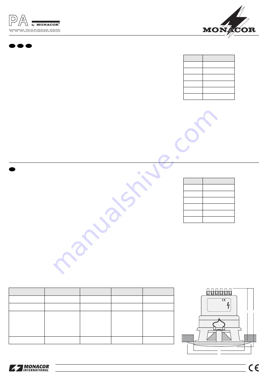
Aderfarbe
Nennbelastung
schwarz
gemeinsamer Anschluss
braun
20 W
rot
15 W
orange
10 W
gelb
5 W
grün
2,5 W
Core Colour
Rated Load
black
common connection
brown
20 W
red
15 W
orange
10 W
yellow
5 W
green
2.5 W
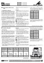
Technische Daten
EDL-206
EDL-204
100 – 18 000 Hz
20/15/10/5/2,5 W
RMS
Frequenzbereich
85 – 18 000 Hz
Ø 132 mm
Ø 104 mm
102 mm
118 mm
820 g
EDL-205
90 – 18 000 Hz
20/15/10/5/2,5 W
RMS
Nennbelastbarkeit
20/15/10/5/2,5 W
RMS
Ø 150 mm
Ø 115 mm
102 mm
120 mm
830 g
Abmessungen
(siehe Abb.)
A – Außendurchmesser
B – Einbauöffnung
C – Einbautiefe
D – Gesamttiefe
Ø 180 mm
Ø 132 mm
110 mm
130 mm
Gewicht
900 g
Specifications
Frequency range
Power rating
Dimensions
(see fig.)
A – outside diameter
B – mounting cutout
C – mounting depth
D – total depth
Weight


