ELA-Druckkammer-
lautsprecher
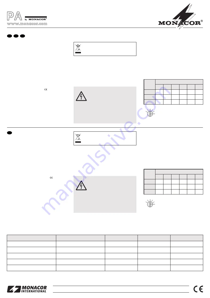
Bitte lesen Sie diese Anleitung vor der Installation
gründlich durch und heben Sie sie für ein späteres
Nachlesen auf.
1 Verwendungsmöglichkeiten
Dieser ELA-Lautsprecher ist speziell für den Einsatz in
ELA-Anlagen konzipiert, die mit 100-V-Technik arbei-
ten. Durch das wetterfeste Gehäuse (IP 66) ist er auch
für den Außenbereich geeignet.
2 Wichtige Hinweise für den sicheren
Gebrauch
Der Lautsprecher entspricht allen relevanten Richtli-
nien der EU und ist deshalb mit
gekennzeichnet.
G
Schützen Sie den Lautsprecher vor großer Hitze
und Kälte (zulässiger Einsatztemperaturbereich
-20 °C bis +50 °C).
G
Verwenden Sie für die Reinigung nur ein trockenes,
oder angefeuchtetes, weiches Tuch, auf keinen Fall
Chemikalien oder scharfe Reinigungsmittel.
G
Wird der Lautsprecher zweckentfremdet, nicht fach-
gerecht angeschlossen oder überlastet, kann keine
Haftung für daraus resultierende Sach- oder Perso-
nenschäden und keine Garantie für den Lautspre-
cher übernommen werden.
3 Montage
Den Lautsprecher mit dem Montagebügel an geeigneter
Stelle festschrauben. Zum Ausrichten die Feststellmut-
tern des Bügels lösen, den Lautsprecher entsprechend
schwenken und die Muttern wieder fest anziehen.
4 Elektrischer Anschluss
WARNUNG
Im Betrieb liegt berührungsgefähr liche
Spannung bis 100 V an der Anschluss -
leitung an. Die Installation darf nur
durch Fachpersonal erfolgen.
Bei der Außenmontage muss der An-
schluss wetterfest ausgeführt werden.
Achten Sie auf die Belastung des ELA-Verstärkers
durch die Lautsprecher. Eine Überlastung kann den
Verstärker beschädigen! Die Summe der Leistungen
aller angeschlossenen Lautsprecher darf die Verstär-
kerleistung nicht überschreiten.
Soll der Lautsprecher endgültig aus dem Be-
trieb genommen werden, übergeben Sie ihn
zur umweltgerechten Entsorgung einem örtli-
chen Recyclingbetrieb.
1) Falls die ELA-Anlage eingeschaltet ist, diese zuerst
komplett ausschalten!
2) Die 100-V-Audioleitung vom ELA-Verstärker an die
weiße und schwarze Ader der Lautsprecherleitung
anschließen. Die grüngelbe Ader an den Schutzlei-
ter anschließen.
3) Beim Anschluss von mehreren Lautsprechern da-
rauf achten, dass die Lautsprecher alle gleich ge-
polt werden (z. B schwarze Ader = Minuspol).
4) Die gewünschte Nennbelastung durch den Laut-
sprecher mit dem Drehschalter auf der Rückseite
einstellen. Mithilfe eines Schraubendrehers den
Schalter in die entsprechende Position drehen:
Schalter in Position 1
Änderungen vorbehalten.
1
2
3
4
5
6
PA Horn Speaker
Please read these operating instructions carefully
prior to installing the speaker and keep them for later
use.
1 Applications
This PA speaker has especially been designed for PA
systems operating with a 100 V technique. Due to the
weatherproof housing (IP 66) it is also suitable for out-
door applications.
2 Safety Notes
The speaker corresponds to all relevant directives of
the EU and is therefore marked with
.
G
Protect the speaker against excessive temperatures
(admissible ambient temperature range -20 °C to
+50 °C).
G
For cleaning only use a dry, soft cloth, never use
chemicals or aggressive detergents.
G
No guarantee claims for the speaker and no liability
for any resulting personal damage or material dam-
age will be accepted if the speaker is used for pur-
poses other than originally intended, if it is not con-
nected in an expert way, or overloaded.
3 Mounting
Tightly screw the speaker with the mounting bracket at
a suitable place. To adjust the speaker, release the
locking nuts of the bracket, move the speaker accord -
ingly, and retighten the nuts.
4 Electrical Connection
1) If the PA system is switched on, first switch it off
completely before connecting it!
WARNING
During operation there is a hazard of
contact at the connection cable with a
voltage of up to 100 V. The installation
must only be carried out by au thorized
personnel.
For outside mounting, the connection must be made
in a weatherproof way.
Observe the load of the speakers on the PA amplifier.
An overload may damage the amplifier! The total
power of all speakers connected must not exceed the
amplifier power.
If the speaker is to be put out of operation de-
fini tively, it must be taken of in a local recy-
cling plant for a disposal which is not harmful
to the environment.
2) Connect the 100 V audio line of the PA amplifier to
the white and black cores of the speaker line. Con-
nect the green-yellow core to the protective con-
ductor.
3) When connecting several speakers, observe that
all speakers are polarized in the same way (e. g.
black core = negative pole).
4) Adjust the desired nominal load by the speaker with
the rotary switch on the rear side. By means of a
screwdriver turn the switch into the corresponding
position:
Switch in position 1
Subject to technical modification.
1
2
3
4
5
6
IT-110
Best.-Nr. 16.1690
IT-115
Best.-Nr. 16.1700
IT-130
Best.-Nr. 16.1710
MONACOR INTERNATIONAL GmbH & Co. KG • Zum Falsch 36 • 28307 Bremen • Germany
Copyright
©
by MONACOR INTERNATIONAL. All rights reserved.
A-0206.99.02.06.2011
®
GB
D
A
CH
Modell
Schalterposition
Technische Daten
IT-130
IT-110
315 – 12 500 Hz
10/5/3/1 W
RMS
Frequenzbereich
250 – 16 000 Hz
105 dB
1,1 kg
IT-115
280 – 12 500 Hz
15/10/5/3/1 W
RMS
108 dB
Nennbelastbarkeit
30/15/10/5/3/1 W
RMS
1,3 kg
Mittlerer Schalldruck (1 W/1 m)
109 dB
Gewicht
1,7 kg
Specifications
Frequency range
Power rating
SPL (1 W/1 m)
Weight
1 W
3 W
IT-130
30 W
15 W
5 W
10 W
—
1 W
IT-115
15 W
10 W
3 W
5 W
—
—
IT-110
10 W
5 W
1 W
3 W
6
5
1
2
4
3
Model
Switch Position
1 W
3 W
IT-130
30 W
15 W
5 W
10 W
—
1 W
IT-115
15 W
10 W
3 W
5 W
—
—
IT-110
10 W
5 W
1 W
3 W
6
5
1
2
4
3
175 × 130 × 185 mm
225 × 160 × 235 mm
Abmessungen ohne Montagebügel
290 × 215 × 260 mm
Dimensions w/o mounting bracket

