background image

48

English

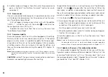
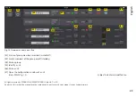
7.3.2  View MAIN 

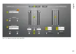
(fig . 13)

[1]  Buttons to switch over the view (change of view only possible at 

the access level “Administrator”)

[2]  UNIT CONNECTION – connection status

green = connected
red  = not connected

[3]  Name of unit; unit can be renamed
[4]  PC PRESET

“SAVE” the current settings as presets on the computer (like 
menu item “File 

Save”) and “LOAD” the presets from the com-

puter (like menu item “File 

Open”)

[5]  SPEAKER PRESET

“SAVE” the current settings as presets in the speaker and “LOAD” 
the presets from the speaker
Select the storage location in the list field and enter a name in 
the upper field .

Note:

  To allow selection of a preset from the group control, save the preset 

to one of the storage locations 10 – 19 .

[6]  INPUT CONTROL for setting the gain (volume) for the inputs, level 

indicators next to the control, input /display fields as a numeric 
input facility beneath the control

[7]  Level indicator MASTER LEVEL for the outputs LF (bass speaker) 

and HF (tweeter)

[8]  LINK switch (for controlling the two input channels together)

Channel IN-B will adopt the settings of channel IN-A .

[9]  MUTE switch for muting the corresponding input
[10] List field to select the unit of measurement for the DELAY value 

[11]: time or distance (for automatic calculation of the delay)

[11] Input /display field DELAY for setting the signal delay of the input 

signals (e . g . to compensate differences in sound delay due to 
different distances of individual speakers to the listening position) 
Alternatively, use the sliding control to set the signal delay .

[12] List field to select the filter type for the high pass filter LOW CUT 

with the following options:

Indication

Filter type

Slope

But 6dB

Butterworth

6 dB/octave

Bes 6dB

Bessel

6 dB/octave

But 12dB

Butterworth

12 dB/octave

Bes 12dB

Bessel

12 dB/octave

L-R 12dB

Linkwitz-Riley

12 dB/octave

But 18dB

Butterworth

18 dB/octave

Bes 18dB

Bessel

18 dB/octave

But 24dB

Butterworth

24 dB/octave

Bes 24dB

Bessel

24 dB/octave

L-R 24dB

Linkwitz-Riley

24 dB/octave

[13] High pass filter LOW CUT: Input /display field for the cut-off  

frequency (enter values in Hz, “Off” < 20Hz) 


Alternatively, use the sliding control to set the frequency .

Summary of Contents for WALL-05DT

Page 1: ...TS ELECTRONICS FOR SPECIALISTS ELECTRONICS FOR SPECIALISTS ELECTRONICS FOR SPECIALISTS BEDIENUNGSANLEITUNG INSTRUCTION MANUAL MODE D EMPLOI ISTRUZIONI PER L USO Aktiver Lautsprecher f r Dante Netzwerk...

Page 2: ...2 2 3 4 2 1 WALL 05DT MONACOR INTERNATIONAL ZUM FALSCH 36 28307 BREMEN GERMANY IN PoE LINK 5 6 7 Abb Fig 1 Abb Fig 2...

Page 3: ...CS FOR SPECIALISTS ELECTRONICS FOR SPECIALISTS ELECTRONICS FOR SPECIALISTS ELECTRONICS FOR SPECIALISTS ELECTRONICS FOR SPECIALISTS ELECTRONICS Deutsch Seite 4 English Page 32 Fran ais Page 60 Italiano...

Page 4: ...Update ber das Men des Konfigurationsfensters 16 7 2 6 Programm beenden 17 7 3 Signalverarbeitung konfigurieren 18 7 3 1 Signalweg 18 7 3 2 Ansicht MAIN 20 7 3 3 Ansicht IN A B 22 7 3 4 Gruppensteueru...

Page 5: ...ss 5 2 Wichtige Hinweise Das Ger t entspricht allen relevanten Richt linien der EU und ist deshalb mit gekennzeichnet Verwenden Sie das Ger t nur im Innenbereich und sch tzen Sie es vor Tropf und Spri...

Page 6: ...lich Die Stromversorgung des Lautsprechers kann ber den Netzwerk anschluss erfolgen Power over Ethernet oder ber ein zus tzliches Netzger t 3 1 Dante Dante ist ein von der Firma Audinate entwickeltes...

Page 7: ...rnet Schnittstellen mit unterschiedlichen IP Adressen Hinweis Bei einer manuellen Festlegung der IP Adressen im lokalen Netzwerk d rfen diese beiden Schnittstellen nicht dieselbe Adresse zugewiesen be...

Page 8: ...etzwerk geschieht ber das Programm Dante Controller das ber die Web site der Firma Audinate kostenlos erh ltlich ist Die ber das Programm vorgenommenen Einstellungen werden in den beteiligten Sendern...

Page 9: ...urchlesen b Durch Anklicken der Check Box I agree die Lizenzverein barung akzeptieren oder die Installation mit dem Close Button abbrechen c Auf den Install Button klicken Abb 5 Dante Controller Lizen...

Page 10: ...handbuch des Dante Controllers von Audinate 3 In der Men leiste des Dante Controllers Device Device View ausw hlen oder die Tastenkombination Strg D dr cken Das Device View Fenster ffnet sich 4 In de...

Page 11: ...anal bis zur Zeile des gew nsch ten Dante Receive Kanals vom WALL 05DT navigieren und auf das Feld klicken 3 Warten bis das Feld einen gr nen Kreis mit wei em Haken anzeigt siehe Abbildung 8 4 Die let...

Page 12: ...g folge und die zugeh rigen Passw rter Zugriffsebene Passwort Administrator mega_adm User monacor Locked State Abb 9 Passwortvorgaben Diese Passw rter sind vom Werk vorgegeben und k nnen vom Anwender...

Page 13: ...X System das Programm MONACOR DSP Controller app starten 7 2 Steuerprogramm aufrufen 1 Auf dem Computer das Steuerprogramm DSP Controller auf rufen 2 Wurde f r das Programm ein Passwort eingerichtet K...

Page 14: ...ware Adresse MAC Adresse der Schnittstelle des Ger ts ber die sich ein Ger t immer eindeutig identifizieren l sst 7 Anzeige der IP Adresse eines Ger ts Bei unterbrochener Verbindung steht an dieser St...

Page 15: ...ionsfenster der Gruppentypen Carbon Copy und Advanced denen f r einzelne Ger te gleichen Kap 7 3 2 und 7 3 3 haben Gruppen vom Typ Master Volume ein spezielles Fenster f r die Steuerung Kap 7 3 4 7 2...

Page 16: ...Lautst rke kommt Um die Firmware eines Ger ts auf den neuesten Stand zu bringen den Men punkt Tools Enable Update aufrufen Hinter den Ger ten in der Liste wird jetzt das Symbol angezeigt Bei einem gra...

Page 17: ...e automatische IP Adressenzuwei sung Network Settings Kap 7 11 zur ckstellt kann auf ein Ger t bei dem zuvor eine feste IP Addresse eingestellt war eventuell vom Computer aus nicht mehr zugegriffen we...

Page 18: ...ll oder der letzte Zustand vor dem Ausschalten Kap 7 7 ber die Schaltfl chen am oberen Rand 1 kann auf die Ansichten der Eingangskan le IN A und IN B Abb 14 umgeschaltet werden Dies ist jedoch nur in...

Page 19: ...iagramm des Signalwegs IN B IN A HF LF D A D A PEQ 1 10 out in LIMITER DELAY GAIN PEQ 1 10 out in LIMITER DELAY GAIN LINK Dante 1 2 PEQ 1 10 out in LIMITER GAIN MUTE PEQ 1 10 out in LIMITER GAIN MUTE...

Page 20: ...echer 8 LINK Schalter zur Kopplung d h zur gemeinsamen Steuerung der beiden Eingangskan le Dabei bernimmt der Kanal IN B die Einstellungen von Kanal IN A 9 MUTE Schalter zum Stummschalten des jeweilig...

Page 21: ...21 Deutsch Abb 13 Konfigurationsfenster in der Ansicht MAIN 1 2 6 7 8 13 9 11 3 4 5 12 10...

Page 22: ...s Bilddatei PNG speichern Feineinstellmodus ein ausschalten Ein Ausblenden der Werte aller aktiven Filter 17 MUTE Schalter zum Stummschalten des entsprechenden Ein gangs gleiche Wirkung wie 9 18 Schal...

Page 23: ...23 Deutsch Abb 14 Ansicht IN A 14 15 16 18 19 20 21 22 17 23 24 25...

Page 24: ...vom Typ Carbon Copy und Advanced kommen die gleichen Konfigurationsfenster zum Einsatz die auch f r die Konfiguration der Einzelger te verwendet werden Kap 7 3 2 und 7 3 3 Welche Parameter in den Kon...

Page 25: ...enmitglieder Die drei Klangregler bestimmen nur den Wert f r die Pegelanhe bung absenkung GAIN beim entsprechenden Filter die brigen Parameter Filterfrequenz Filtertyp und G te bleiben f r jedes Filte...

Page 26: ...Ebene nur ber die Ein gabe eines korrekten Passworts einer h heren Ebene wieder verlassen werden kann Die Meldung mit OK best tigen 7 6 Standby Um das Ger t in den Bereitschaftsmodus Standby zu verse...

Page 27: ...ets und die Firmware eines Ger ts in einer Flash Image Datei gespeichert werden Dazu den Men punkt File Create Flash Image aufrufen und einen Dateinamen und Spei cherort w hlen Das Laden einer solchen...

Page 28: ...ske eingeben 5 Mit Klick auf den Ok Button best tigen Um dem Ger t automatisch eine IP Adresse zuweisen zu lassen 1 Den Men punkt Hardware Configure Network Settings auf rufen 2 Configure Network Auto...

Page 29: ...500Hz Filtertypen Butterworth Linkwitz Riley Bessel Filtersteilheit 6 24dB Oktave Delay max 40ms Signalbearbeitungsm glichkeiten je Eingangskanal Gain 50dB bis 6dB Parametrischer Equalizer Filteranza...

Page 30: ...Steuerung von mehreren Stellen aus ist auch wenn unterschiedliche Ger te innerhalb eines Netzwerks ge steuert werden sollen nicht m glich Die Ger te bersicht weicht etwas von der in den Kapiteln 7 2...

Page 31: ...t Abb 18 Ger te bersicht auf einem iPad 43 34 33 44 46 36 37 38 35 42 39 40 45 41 47 42 Status der Gruppenmitglieder Gruppenmitglieder stummge schaltete Ger te ausgeschaltete Ger te 43 Ger te der Grup...

Page 32: ...7 2 5 1 Update via the menu of the configuration window 44 7 2 6 Exiting the program 45 7 3 Configuring the signal processing 46 7 3 1 Signal path 46 7 3 2 View MAIN 48 7 3 3 View IN A B 50 7 3 4 Grou...

Page 33: ...to all relevant directives of the EU and is therefore marked with The unit is suitable for indoor use only Protect it against dripping water splash water and high air humidity The admissible ambient...

Page 34: ...with power via the network connection Power over Ethernet or via an additional power supply unit 3 1 Dante Dante an audio network developed by the company Audinate allows transmission of up to 512 aud...

Page 35: ...erface of WALL 05DT is preset to automatic reception of an IP address If a DHCP server is available in the network connected the speaker will receive its address from the server If an ordinary Etherne...

Page 36: ...that the program is only required for network configuration but not for normal operation The following system requirements apply to the computer on which the program Dante Controller is to be executed...

Page 37: ...oller Setup b Click the check box I agree to accept or click the button Close to cancel the installation c Click the button Install Fig 5 Licence agreement of the Dante Controller d Note and accept th...

Page 38: ...switch For further information please refer to the user manual of the Dante Controller from Audinate 3 In the menu bar of the Dante Controller select Device Device View or use the shortcut Ctrl D The...

Page 39: ...Dante transmit channel to the line of the desired Dante receive channel of WALL 05DT and click the field 3 Wait for the field to show a green circle with a white check mark refer to fig 8 4 Repeat the...

Page 40: ...orresponding passwords Access level Password Administrator mega_adm User monacor Locked State Fig 9 Default passwords The passwords are factory set and can be changed by the user at the corre sponding...

Page 41: ...program MONA COR DSP Controller app 7 2 Calling up the control program 1 Call up the control program DSP Controller on the computer 2 If a password has been assigned to the program chapter 7 2 2 a wi...

Page 42: ...it 7 Indication of the IP address of a unit When the connection is interrupted Offline is indicated here 8 Button to call up the configuration window fig 13 for a unit which is on line In the line All...

Page 43: ...Volume have a specific control window chapter 7 3 4 7 2 1 2 Deleting a group To delete a group click the button in the corresponding line fig 11 A confirmation box will appear asking you to confirm t...

Page 44: ...s to prevent unexpected high volumes after resetting To update the firmware of a unit call up the menu item Tools Enable Update An icon will appear after the units in the list When the icon is grey an...

Page 45: ...ware update will be made and then a factory file will be loaded A firmware update will reset the unit to automatic IP address assignment Network Settings chapter 7 11 Therefore the computer may no lon...

Page 46: ...t can be defined if a specific preset or the previous settings will be loaded when the unit is switched on chapter 7 7 The buttons at the top 1 can be used to switch to the views of the input channels...

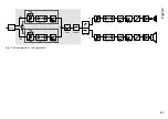
Page 47: ...agram of the signal path IN B IN A HF LF D A D A PEQ 1 10 out in LIMITER DELAY GAIN PEQ 1 10 out in LIMITER DELAY GAIN LINK Dante 1 2 PEQ 1 10 out in LIMITER GAIN MUTE PEQ 1 10 out in LIMITER GAIN MUT...

Page 48: ...itch for controlling the two input channels together Channel IN B will adopt the settings of channel IN A 9 MUTE switch for muting the corresponding input 10 List field to select the unit of measureme...

Page 49: ...49 English Fig 13 Configuration window in the view MAIN 1 2 6 7 8 13 9 11 3 4 5 12 10...

Page 50: ...reduce the view Save curves as image file PNG Fine adjustment on off Show hide the values of all active filters 17 MUTE switch to mute the corresponding input same effect as 9 18 Switch ON to activate...

Page 51: ...51 English Fig 14 View IN A 14 15 16 18 19 20 21 22 17 23 24 25...

Page 52: ...of units of the type Carbon Copy and Advanced the same configuration windows like for configuring the individual units are used chapters 7 3 2 and 7 3 3 It depends on the settings of the individual gr...

Page 53: ...and IN B of all group members The three equalizer controls only define the value for boosting attenuating the level GAIN for the corresponding filter the other parameters filter frequency filter type...

Page 54: ...to enter the correct password of a higher level before you are able to exit the present level Confirm this message with OK 7 6 Standby To set the unit to Standby call up the menu item Hardware Go to...

Page 55: ...and the firmware of a unit can be saved to a flash image file Call up the menu item File Create Flash Image and select a file name and a storage location Such a file can be loaded via the menu item Fi...

Page 56: ...Enter the desired subnet mask 5 Click OK to confirm To automatically assign an IP address to the unit 1 Call up the menu item Hardware Configure Network Settings 2 Click Configure Network Automaticall...

Page 57: ...cy 20 500Hz Filter types Butterworth Linkwitz Riley Bessel Slope 6 24dB octave Delay 40ms max Signal processing options for each input channel Gain 50dB to 6dB Parametric equalizer Number of filters 1...

Page 58: ...trol from multiple locations is not possible even if different units are to be controlled within a network The overview of units slightly differs from the view described in chap ters 7 2 and 7 2 1 Fig...

Page 59: ...tch members of the group on off standby 44 Mute a group 45 Identify a unit 46 Mute a unit 47 Open the configuration window of a unit view MAIN fig 13 Subject to technical modification All rights reser...

Page 60: ...fen tre de configuration 72 7 2 6 Quitter le programme 73 7 3 Configuration du traitement du signal 74 7 3 1 Voie de signal 74 7 3 2 Visualisation MAIN 76 7 3 3 Visualisation IN A B 78 7 3 4 G rer de...

Page 61: ...e L appareil n est con u que pour une utilisation en int rieur Pro t gez le des claboussures de tout type de projections d eau et d une humidit lev e de l air La plage de temp rature ambiante admissib...

Page 62: ...ion de l enceinte peut se faire soit via la connexion r seau Power over Ethernet soit via un bloc secteur suppl mentaire 3 1 Dante Dante est un r seau audio d velopp par la soci t Audinate avec lequel...

Page 63: ...ec des adresses IP diff rentes Remarque Dans le cas d une d finition manuelle des adresses IP dans le r seau local ces deux interfaces ne doivent pas avoir la m me adresse L interface DSP de la WALL 0...

Page 64: ...t via le programme Dante Controller disponible gratuitement via le site internet de la soci t Audinate Les r glages effectu s via le programme sont m moris s dans les metteurs et r cepteurs par ticipa...

Page 65: ...tre Dante Controller Setup b En cochant la case I agree vous acceptez les indications de la licence ou bien arr tez l installation avec le bouton Close c Cliquez sur le bouton Install Sch ma 5 Valida...

Page 66: ...nte Controller de Audinate 3 Dans la barre de menu du Dante Controller s lectionnez Device Device View ou appuyez sur la combinaison de touches Ctrl D La fen tre Device View s affiche 4 Dans la barre...

Page 67: ...Dante Transmit jusqu la ligne du canal Dante Receive souhait de la WALL 05DT et cliquez sur le champ 3 Attendez jusqu ce que le champ affiche un cercle vert coch en blanc voir sch ma 8 4 Effectuez le...

Page 68: ...e d croissant et les mots de passe correspondants Niveau d acc s Mot de passe Administrator mega_adm User monacor Locked State Sch ma 9 Mots de passe pr r gl s Ces mots de passe sont pr r gl s en usin...

Page 69: ...marrez le pro gramme MONACOR DSP Controller app 7 2 Appeler le programme de commande 1 Sur l ordinateur appelez le programme de commande DSP Controller 2 Si un mot de passe a t cr pour le programme ch...

Page 70: ...se MAC de l interface de l appareil via laquelle un appareil peut toujours tre identifi de mani re unique 7 Affichage de l adresse IP d un appareil En cas de connexion interrompue Offline est visible...

Page 71: ...des appareils individuels chapitres 7 3 2 et 7 3 3 les groupes de type Master Volume ont une fen tre sp cifique pour la gestion chapitre 7 3 4 7 2 1 2 Effacer un groupe Pour effacer un groupe cliquez...

Page 72: ...des r glages Pour faire la mise jour du firmware d un appareil appelez le point de menu Tools Enable Update Derri re les appareils dans la liste le symbole s affiche Si le symbole est gris aucune mise...

Page 73: ...e r initialise l appareil sur une attribution automatique d adresse IP Network Settings chapitre 7 11 il est possible que vous n ayez plus acc s depuis l ordinateur un appareil sur lequel une adresse...

Page 74: ...charg ou si le dernier tat avant l arr t pr vaut chapitre 7 7 Via les boutons dans la rang e sup rieure 1 vous pouvez commuter sur les visualisations des canaux d entr e IN A et IN B sch ma 14 Cela n...

Page 75: ...bloc de la voie de signal IN B IN A HF LF D A D A PEQ 1 10 out in LIMITER DELAY GAIN PEQ 1 10 out in LIMITER DELAY GAIN LINK Dante 1 2 PEQ 1 10 out in LIMITER GAIN MUTE PEQ 1 10 out in LIMITER GAIN M...

Page 76: ...coupler c est dire pour une gestion commune les deux canaux d entr e Le canal IN B reprend les r glages du canal IN A 9 Interrupteur MUTE pour couper le son de l entr e correspondante 10 Champ pour s...

Page 77: ...77 Fran ais Sch ma 13 Fen tre de configuration dans la visualisation MAIN 1 2 6 7 8 13 9 11 3 4 5 12 10...

Page 78: ...avec m moriser des courbes sous forme de fichier image PNG activation d sactivation du mode de r glage pr cis affichage pas d affichage des valeurs de tous les filtres activ s 17 Interrupteur MUTE po...

Page 79: ...79 Fran ais Sch ma 14 Visualisation IN A 14 15 16 18 19 20 21 22 17 23 24 25...

Page 80: ...es groupes d appareils de type Carbon Copy et Advanced on utilise les m mes fen tres de configuration que celles pour la configuration des appareils individuels chapitres 7 3 2 et 7 3 3 Les param tres...

Page 81: ...membres du groupe Les trois r glages de tonalit d finissent uniquement la valeur pour l augmentation diminution de niveau GAIN pour le filtre correspondant les autres param tres fr quence du filtre t...

Page 82: ...signalant que ce niveau ne peut tre quitt qu en saisissant un mot de passe correct d un niveau sup rieur Confirmez le message avec OK 7 6 Standby Pour mettre l appareil sur le mode veille Standby app...

Page 83: ...resets et le firmware d un appareil sous forme de fichier Flash Image Appelez le point de menu File Create Flash Image et s lectionnez un nom de fichier et un emplacement Le chargement d un tel fichie...

Page 84: ...eau voulu 5 Confirmez en cliquant sur Ok Pour faire attribuer automatiquement une adresse IP l appareil 1 Appelez le point de menu Hardware Configure Network Set tings 2 Cliquez sur Configure Network...

Page 85: ...haut Fr quence limite 20 500Hz Types de filtre Butterworth Linkwitz Riley Bessel Pente 6 24dB octave Delay 40ms max Possibilit s de traitement du signal par canal d entr e Gain 50dB 6dB Egaliseur para...

Page 86: ...t pas possible m me si des appareils distincts doivent tre g r s au sein d un r seau La pr sentation des appareils est un peu diff rente de celle d crite dans les chapitres 7 2 et 7 2 1 Le sch ma 17 p...

Page 87: ...Allumer teindre les appareils du groupe Standby 44 Couper le son d un groupe 45 Identifier un appareil 46 Couper le son d un appareil 47 Ouvrir la fen tre de configuration d un appareil visualisation...

Page 88: ...100 7 2 5 1 Update attraverso il menu della finestra di configurazione 100 7 2 6 Terminare il programma 101 7 3 Configurare l elaborazione dei segnali 102 7 3 1 Percorso dei segnali 102 7 3 2 Vista MA...

Page 89: ...nti L apparecchio conforme a tutte le direttive rilevanti dell UE e pertanto porta la sigla Usare l apparecchio solo all interno di locali e proteggerlo dall acqua gocciolante e dagli spruzzi d acqua...

Page 90: ...altoparlante pu essere fatta tramite la connes sione rete Power over Ethernet oppure tramite un alimentatore sup plementare 3 1 Dante Dante una rete audio sviluppata dalla societ Audinate che rende po...

Page 91: ...assegnato lo stesso indirizzo L interfaccia DSP del WALL 05DT preimpostata per la ricezione au tomatica di un indirizzo IP Se nella rete collegata presente un server DHCP l altoparlante riceve il suo...

Page 92: ...e nei trasmettitori e ricevitori interessati cos il programma necessario soltanto per la configurazione della rete ma non durante il funzionamento normale Il computer sul quale deve essere installato...

Page 93: ...del Dante Controller b Cliccando sulla check box I agree per accettare l accordo di licenza oppure interrompere l installazione con il pulsante Close c Cliccare sul pulsante Install Fig 5 Accordo di...

Page 94: ...azioni si trovano nel manuale del Dante Controller di Audinate 3 Nella riga del menu del Dante Controller scegliere Device Device View oppure premere i tasti Ctrl D Si apre la finestra Device View 4 N...

Page 95: ...ante Transmit navigare fino alla riga del canale Dante Receive del WALL 05DT e cliccare sul campo 3 Aspettare che il campo visualizzi un cerchio verde con segno di spunta bianco vedi figura 8 4 Gli ul...

Page 96: ...ccesso in ordine decrescente con i relativi password Livello d access Password Administrator mega_adm User monacor Locked State Fig 9 Password preimpostate Queste password sono preimpostate dalla fabb...

Page 97: ...stema Mac OS X avviare il programma MONACOR DSP Controller app 7 2 Aprire il programma di comando 1 Sul computer aprire il programma DSP Controller 2 Se per il programma prevista una password Cap 7 2...

Page 98: ...zione dell indirizzo hardware indirizzo MAC dell interfaccia dell apparecchio con il quale un apparecchio pu sempre essere identificato chiaramente 7 Indicazione dell indirizzo IP di un apparecchio Se...

Page 99: ...le finestre di configurazione dei tipi Carbon Copy e Advanced somigliano a quelle per apparecchi singoli Cap 7 3 2 e 7 3 3 i gruppi del tipo Master Volume hanno una finestra specifica per il comando C...

Page 100: ...spettatamente alto dopo il reset delle impostazioni Per aggiornare il firmware di un apparecchio aprire la voce del menu Tools Enable Update Dietro gli apparecchi dell elenco si vede ora il simbolo Se...

Page 101: ...chio un assegnazione automatica dell indirizzo IP Network Settings Cap 7 11 possibile che dal computer non si possa pi accedere a un apparecchio sul quale era stato impostato prima un indirizzo IP fis...

Page 102: ...l apparecchio deve essere caricato sempre un determinato preset oppure l ultimo stato di funzionamento prima dello spegnimento Cap 7 7 Con i pulsanti al bordo superiore 1 si pu cambiare la vista dei c...

Page 103: ...occhi del percorso dei segnali IN B IN A HF LF D A D A PEQ 1 10 out in LIMITER DELAY GAIN PEQ 1 10 out in LIMITER DELAY GAIN LINK Dante 1 2 PEQ 1 10 out in LIMITER GAIN MUTE PEQ 1 10 out in LIMITER GA...

Page 104: ...ttore LINK per accoppiare comando comune i due canali d ingresso Il canale IN B prende le impostazioni del canale IN A 9 Interruttore MUTE per la messa in muto del relativo ingresso 10 List box per sc...

Page 105: ...105 Italiano Fig 13 Finestra di configurazione nella vista MAIN 1 2 6 7 8 13 9 11 3 4 5 12 10...

Page 106: ...urve come file immagini PNG attivare disattivare il modo di impostazione fine visualizzare nascondere i valori di tutti i filtri attivi 17 Interruttore MUTE per la messa in muto del relativo ingresso...

Page 107: ...107 Italiano Fig 14 Vista IN A 14 15 16 18 19 20 21 22 17 23 24 25...

Page 108: ...l comando dei gruppi del tipo Carbon Copy e Advanced si usano le stesse finestre di configurazione come per la configurazione degli apparecchi singoli Cap 7 3 2 e 7 3 3 Il fatto quali parametri posson...

Page 109: ...d ingresso IN A e IN B di tutti i membri del gruppo I tre regolatori toni determinano soltanto il valore per l aumento abbassamento del livello GAIN nel relativo filtro i restanti para metri frequenz...

Page 110: ...olo digitando la password corretta di un livello superiore Confermare il messaggio con OK 7 6 Standby Per mettere l apparecchio nel modo standby aprire la voce del menu Hardware Go to Standby Per il r...

Page 111: ...il firmware di un apparecchio possono essere memorizzati in un file Flash image Per fare ci aprire la voce del menu File Create Flash Image e scegliere un nome file e una locazione di memoria Il cari...

Page 112: ...net 5 Confermare cliccando sul pulsante Ok Per fare assegnare un indirizzo IP automatico 1 Aprire la voce del menu Hardware Configure Network Settings 2 Cliccare su Configure Network Automatically 3 C...

Page 113: ...i Butterworth Linkwitz Riley Bessel Pendenza dei filtri 6 24dB ottava Delay max 40ms Possibilit d elaborazione dei segnali per ogni canale d ingresso Gain 50dB a 6dB Equalizer parametrico Numero filtr...

Page 114: ...punti non possibile anche se si devono comandare differenti apparecchi all interno di una rete La vista degli apparecchi si discosta leggermente dalla vista descritta nei capitoli 7 2 e 7 2 1 La figu...

Page 115: ...del gruppo Standby 44 Messa in muto del gruppo 45 identificare un apparecchio 46 Messa in muto di un apparecchio 47 Aprire la finestra di configurazione di un apparecchio Vista MAIN fig 13 Con riserv...

Page 116: ...MONACOR INTERNATIONAL GmbH Co KG Zum Falsch 36 28307 Bremen Germany Copyright by MONACOR INTERNATIONAL All rights reserved A 1823 97 01 03 2017...

Reviews: