background image

BRAKE CORD/BELT
REPLACEMENT

Remove the instrument cover by loosen the screws
on each side of the cover.
Take the return strap, see fig. 11, and lift up the
weight basket until it locks in its upper position.
Loosen the cord/belt bracket, see fig. 11, and take
away the brake belt from the tension center.
Loosen or cut away the knot or tie up the knot at
the other end of the belt. After that take away the
belt from the bike.
When assembling a new brake cord/belt, first
enter one end into the belt whole in the tension
center, see fig. 11, and tie a knot and let the knot
fall into the bigger part of the hole.
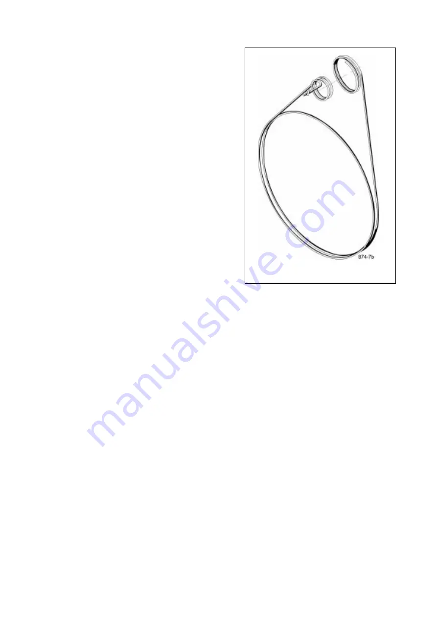
Then assemble the new belt exactly as the old one.
See fig. 10.

NOTE! When replacing the brake cord/belt it
is recommended to clean the brake surface.
See BRAKE SURFACE  - BRAKE BELT.

Fig. 10

11

ADJUSTING THE BRAKE CORD/BELT TENSION

At first check that the brake belt is lying correct on the flywheel brake surface.
See fig. 10 and 11.

Put 4 kg in the weight basket. Rotate the flywheel by hand. The basket shall now lift up so the
distance to the flywheel is at least 40 mm. and maximum 80 mm. If this is not the case the brake
belt has to be loosened or tightened a little at the tension center. If the basket is too low shorten
the belt somewhat and if the basket is too high lenghten the cord somewhat.

Lock the weight basket in its upper position and after that loosen the cord bracket somewhat so
that the cord length can be adjusted.  Tighten the braket again and release and check if the
measurements above are OK when the flywheel is rotated by hand.
Repeat the above if necessary.

Note: The basket will always give the correct workload wherever it hangs between the upper stop
position and the lower stop just above the flywheel. The measurements above just gives a good
margin - about 30 mm in each direction.

Summary of Contents for Ergomedic 874 E

Page 1: ...MANUAL Monark Ergometer 874E...

Page 2: ......

Page 3: ...g 11 Brake surface flywheel 12 Chain 13 Crank bearing 15 Elektronic meter 9 Flywheel bearing 15 General 4 General about exercise 15 16 Operation instruction 8 Replacement adjustment brake belt 11 Repl...

Page 4: ...ge 6 WARRANTY As on any quality product there may be an exceptional fault due to material or manufacture If such a fault should arise on your exercise cycle please return to the place of purchase for...

Page 5: ...PARTS BELOW ARE NOT ASSEMBLED ASSEMBLY INSTRUCTION See pages 5 7 HANDLEBAR HANDLEBAR STEM PEDAL LEFT PEDAL RIGHT SUPPORTING TUBE FRONT SUPPORTING TUBE REAR WEIGHT HOLDER 5...

Page 6: ...en the expanding bolt firmly by means of the le ver NOTE The handlebar stem should be inserted into the frame tube at least 3 inches about 8 cm See fig 4 Usually this measure is marked out on the stem...

Page 7: ...the crank counter clockwise Tighten firmly See fig 5 NOTE Check now and then that both pedals are still firmly tightened If not the threading in the pedal arms will be damaged Also check that the ped...

Page 8: ...conds TIME cycling speed in km per hour or miles per hour SPEED covered distance in km or mile DISTANCE burned Calories CAL and the power workload on the cycle WATT The watt reading is depending on th...

Page 9: ...seconds To get correct raedings for calories and watts the kp value on the electronic meter has to be set to the same value as the workload that is the weight of the basket including the weights in it...

Page 10: ...g 9 If needed the complete fitness computer can be taken out from the panel by loosing the upper fastening plate on the down side of the meter panel Lift in the upper end of the meter and take it out...

Page 11: ...BRAKE CORD BELT TENSION At first check that the brake belt is lying correct on the flywheel brake surface See fig 10 and 11 Put 4 kg in the weight basket Rotate the flywheel by hand The basket shall...

Page 12: ...ur face of the flywheel should then be ground off with a fine sand paper and any dust removed with a clean dry cloth Lift the weight basket to its upper stop position Grind with a fine sand paper See...

Page 13: ...t is worn out and shall be replaced with a new one ADJUSTING CHAIN Remove left and right frame cover To adjust the chain the hub nuts should be loosened Loosening or tightening the nuts on the chain a...

Page 14: ...ial remover part No 9100 14 in the adapter and place the spacer and axle nut outside See fig 15 NOTE Do not tighten the axle nut completely It must be possible to loosen the adapter sprocket half a tu...

Page 15: ...ays the body got its exercise both in work and at leisure In our modern society however machines have taken over an ever increasing share of the tasks which were formerly accomplished with muscular po...

Page 16: ...the equivalent of 20 pounds of body fat You will achieve best results if you combine exercise with healthier eating A little less sugar less butter on your bread or less fat in your frying pan And a f...

Page 17: ...78050 Vansbro 432 82 Varberg Tel 46 0281 594940 Fax 46 0340 80485...

Reviews: