background image

12

BRAKE CORD/BELT REPLACE

-

MENT

Remove the instrument cover by loosen the 

screws on each side of the cover.

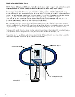
Pull the weight basket return grip, see fig. 8, or 

the return strap, see fig. 13 page 13, and lift up the 

weight basket until it locks in its upper position.

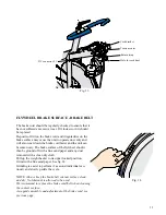
Loosen the cord/belt bracket, see fig. 13, and take 

away the brake belt from the tension center.

Loosen or cut away the knot or tie up the knot at 

the other end of the belt. After that take away the 

belt from the bike.

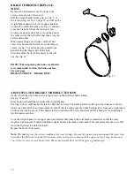
When assembling a new brake cord/belt, first 

enter one end into the belt whole in the tension 

center, see fig. 13, and make a knot and let the 

knot fall into the bigger part of the hole.

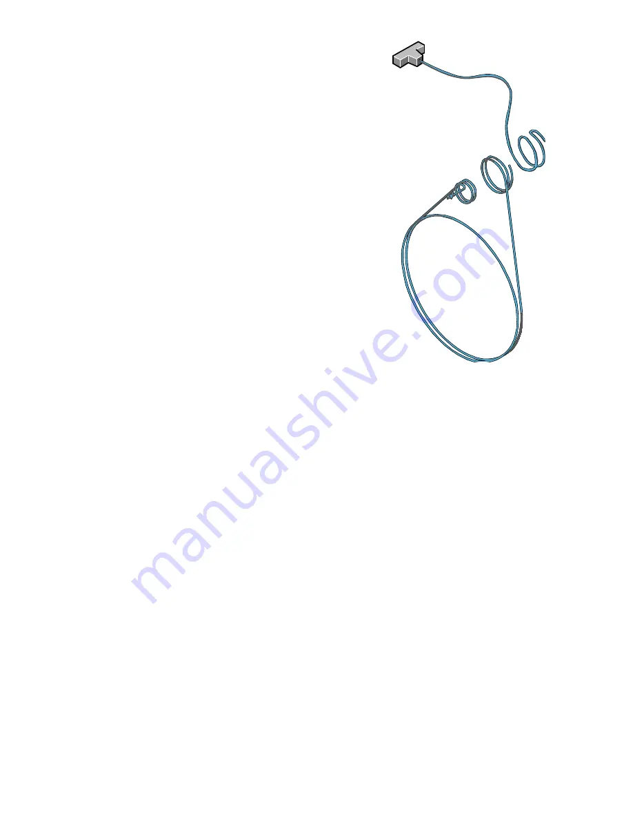
Then assemble the new belt exactly as the old 

one. See fig. 12.

NOTE! When replacing the brake cord/belt it 

is recommended to clean the brake surface.

See next page

BRAKE SURFACE  - BRAKE BELT.


ADJUSTING THE BRAKE CORD/BELT TENSION

At first check that the brake belt is lying correct on the flywheel brake surface.

See fig. 12 and 13. 

Press button on handlebar to release the weight basket.

Put 4 kg in the weight basket. Rotate the flywheel by hand. The basket shall now lift up so the distance to the fly

-

wheel is at least 40 mm. and maximum 60 mm. If this is not the case the brake belt has to be loosened or tightened 

a little at the tension center. If the basket is too low shorten the belt somewhat and if the basket is too high lengh-

ten the cord somewhat.

Lock the weight basket in its upper position and after that loosen the cord bracket somewhat so that the cord 

length can be adjusted.  Tighten the braket again. Release the basket and check if the measurements above are OK 

when the flywheel is rotated by hand.

Repeat the above if necessary.

Note:


The basket gives the correct workload wherever it hangs between the upper stop position and the lower stop 

just above the flywheel. Note that the tension center can’t get in contact with it’s upper or lower stop. In that case 

you will not receive correct brake level. The measurements above (40-60) gives a good margin.

Fig. 12

Summary of Contents for Sprint Bike Ergomedic 884E

Page 1: ...MANUAL English Svensk...

Page 2: ...Chain 14 Crank bearing 15 Elektronic meter 8 Flywheel bearing 15 General 3 General about exercise 16 17 Freewheel lubrication 15 Operation instruction 6 Replacement adjustment brake belt 12 Replaceme...

Page 3: ...If such a fault should arise on your exercise cycle please return to the place of purchase for necessary repair Monark products and parts are guaranteed against defects in materials and workmanship f...

Page 4: ...ig 5 Fig 4 Sadle bracket Post bolt Fig 5 min 3 Before the handlebar stem is assembled be sure the expanding wedge is loose Insert the hand lebar stem into the frame tube and tighten the expanding bolt...

Page 5: ...e pedal axle has a left hand thread and must be threaded onto the crank counter clockwise Tighten firmly See fig 6 NOTE Check now and then that both pedals are still firmly tightened If not the thread...

Page 6: ...and does then not give any work load at all The weight basket is released by pushing the release button on the handlebar When pedalling the subject stores energy in the flywheel The flywheel is then b...

Page 7: ...ests with a duration of 7 seconds After a completed test a value is presented on the display This test value can then be used to compare the ana erobic capacity from time to time The test value can af...

Page 8: ...tion is turned off the symbol is not lit any more The heart rate function can be turned on again by preessing a button Timer starts automatically when pedals are moved Meter values for Time Distance a...

Page 9: ...needed the complete fitness computer can be taken out from the panel by loosing the upper fastening plate on the down side of the meter panel Lift in the upper end of the meter and take it out from t...

Page 10: ...d start position Action Pull the return grip see fig 8 page 6 or the return strap on the front of the bike see fig 13 page 13 until the locking lever locks and the weight basket stops in its upper sta...

Page 11: ...f 1kg each The weight basket itself weighs 1 kg This makes a total brake force of 5 kp 5kg of weight The avarage braking power is then 100 x 5 500 watts The test value stays on the display until the w...

Page 12: ...belt is lying correct on the flywheel brake surface See fig 12 and 13 Press button on handlebar to release the weight basket Put 4 kg in the weight basket Rotate the flywheel by hand The basket shall...

Page 13: ...er and any dust removed with a clean dry cloth Pull up the weight basket to its upper locked position Grind with a fine sand paper See fig 14 Grinding is easier to perform if a second individual cau t...

Page 14: ...ve left and right frame cover To adjust the chain the hub nuts should be loosened Loosening or tightening the nuts on the chain adjusters will then move the hub and axle forward or backward Adjust acc...

Page 15: ...the adapter sprocket half a turn Replace sprocket adapter and assemble the new parts in reverse order according to the above LUBRICATION SPROCKET The sprocket should be lubricated with a few drops of...

Page 16: ...habitual physical activity also improves the wellbeing and it is a good feeling to have a poten tial to cope with straining situations SERVICE CHECKLIST Check the chain is snug and there is no play o...

Page 17: ...DO I TRAIN 1 Warm up 3 5 minutes with a low pedal resistance Pedal about 12 mph 20 km h 2 Increase the resistance until you feel the training somewhat hard Keep the speed for 2 5 minutes Get off the E...

Page 18: ...18 Notes...

Page 19: ...17 Notes...

Page 20: ...Kroons v g 1 SE 78050 Vansbro Sweden Tel 46 0 281 594 940 Fax 46 0 281 719 81 www monarkexercise se...

Reviews: