Technical service manual
7
UK
- A series of wheel spins can be carried out without exiting from the program.
- To exit from the program (and the Service environment) press the “F” key.
The program is used to:
- check that the values displayed are within the permitted ranges, as follows:
• synchronisation difference
F
from -2.0 to +2.0
• internal pick up signal
I
from 200 to 280
• external “
“
E
from 110 to 170
97 F Displaying search circuit board functions (encoder)
Selecting the program displays:
- the message “Pos” on the left-hand display.
- a numerical value between 0 and 255 on the right-hand display as the angle of the
shaft varies.
If the program is recalled immediately after the machine is switched on, the display
shows the message “Pos rot” to indicate that the shaft has to be turned until the en-
coder zero mark has passed in front of the search circuit board: at this point the mes-
sage disappears.
It is also possible to perform a wheel spin (the message “97 GO” appears on the dis-
play) during which the pulses counted by the search board are read. At the end of the
wheel spin the left-hand display shows the expected count value (256) while the value
actually counted flashes on the right-hand display. These values are displayed for
about five seconds, after which the shaft’s current angle appears.
To exit from the program (and the Service environment) press the “F” key.
The program is used to:
- check the efficiency of the search circuit board. When the shaft is turned in either di-
rection, the count must change continuously from 0 to 255, and at the end of a wheel
spin the two values displayed must be the same.
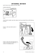
98 Visualisation of internal sensor functions
The selection of the programme determines the visualisation:
- of the “di” message on the left display;
- of the value in notches deriving from the diameter sensor on the right display.
Moving the lever of the sensor, the value is continuously updated.
Pressing the key to set the keypad wheel data, you will see:
- the message “d” on the left display;
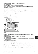
- the value in notches deriving from the distance sensor (1 notch = 0.5mm).
This value is updated by moving the sensor “in - out”.
Pressing the key to set the keypad wheel data, you will see:
- the message “FC” on the left display;
- the message “0-0” on the right display that indicates the status of the zero sensors
used for the zero-setting of the automatic sensor.
Specifically, the message on the left hand side is relative to the distance zero posi-
tion sensor, while the message on the right is relative to the diameter zero position
microswitch.
This message changes to “1-1” when the internal sensor is extracted and returns to
“0-0” when it returns to the rest position. If this update does not occur, carry out the
Summary of Contents for MT 2450
Page 1: ...MT 2450 Code 4 131046_uk 12 2013 Technical service manual...
Page 25: ...Technical service manual 25 UK Note...
Page 27: ...Technical service manual 27 UK...
Page 28: ...28 Technical service manual...
Page 29: ...Technical service manual 29 UK Cod 4 101700...
Page 30: ...30 Technical service manual...
Page 31: ...Technical service manual 31 UK...
Page 32: ...32 Technical service manual...
Page 33: ...Technical service manual 33 UK Cod 457674B...
Page 34: ...34 Technical service manual...


